
Chute damping device for concrete pouring and mounting and using method thereof

A damping device and concrete technology, which is applied in the direction of construction, building structure, and building material processing, etc., can solve the problem that the inner wall corrugated damping effect is poor and cannot meet the requirements of concrete construction technical specifications, the length of the joint cannot meet the construction needs, the degree is small and the Issues such as no more than 2m

Pending Publication Date: 2019-05-21
中国人民解放军63926部队
View PDF0 Cites 0 Cited by
  • Summary
  • Abstract
  • Description
  • Claims
  • Application Information

AI Technical Summary

Problems solved by technology

[0002] Concrete construction has always occupied a large proportion in the civil engineering industry. The traditional methods of concrete transportation in concrete construction mainly use tower crane tank transportation or pumping. These traditional methods are only suitable for small concrete volumes and small concrete dump heights. If it exceeds 2m, for the large-volume steel frame reinforced concrete structure, it is far from meeting the requirement that the concrete fall height does not exceed 2m. Usually, the chute to be used for concrete pouring is HDPE steel belt reinforced double-wall corrugated pipe, with different specifications and models. Usually it is appropriate to use 300mm, the whole length is 12m, and the end of the corrugated pipe is tied with hemp rope when in use, and the operation is completed by vertical or horizontal transport machinery
[0003] According to the existing technical situation and the actual situation of pouring concrete in large-volume steel frame concrete structures, there are the following objective shortcomings: the length control of the HDPE steel belt reinforced double-wall corrugated pipe is not flexible enough, the length of the connection cannot meet the construction needs, and the inner wall corrugation is relatively shallow. Damping effect It is poor and cannot meet the requirements of the construction technical specification that the free fall height of concrete should not exceed 2m, and the connection between the end of the corrugated pipe and the vertical or horizontal transport machinery is relatively simple and easy to slip, posing a safety hazard

Method used


Image

  • Chute damping device for concrete pouring and mounting and using method thereof
  • Chute damping device for concrete pouring and mounting and using method thereof
  • Chute damping device for concrete pouring and mounting and using method thereof

Examples


Embodiment 1

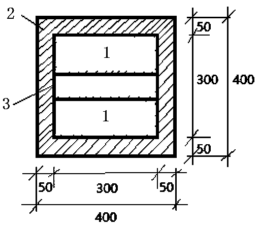
[0032] Such as Figure 1~3 As shown, a chute damping device for concrete pouring is composed of at least two identical chute dampers connected by flanges; the chute damper includes a chute cylinder 3, a flange 2, and a damping guide plate 1; the chute cylinder 3 is a cuboid welded by 4 identical rectangular steel plates with open ends; the rectangular steel plates constituting the chute damper are 2m in length, 294mm in width and 6mm in thickness; (294mm+6mm) square; the damping and guiding steel plate 1 is welded inside the chute cylinder 3, the damping and guiding steel plate 1 is a rectangular steel plate, the length of the short side of the damping and guiding steel plate 1 is 150mm, and the length of the long side is 294mm , with a thickness of 6 mm; the long side of the damping guide plate 1 is perpendicular to the central axis of the chute cylinder 3 (the line connecting the centers of the two open ends of the cuboid of the chute cylinder, not shown in the figure) and w...

Embodiment 2

[0037] This embodiment is the method for installing and using the chute damping device for pouring concrete in Embodiment 1.

[0038] Include the following steps:

[0039] 1) The truck crane is parked in place at the concrete pouring construction site;

[0040] 2) The first chute damper is hoisted in place;

[0041] 3) Use the vertical assembly method to install the second chute damper with bolt connection;

[0042] 4) Install other chute dampers in sequence according to the required lengths;

[0043] 5) Lift the installed chute damper to the concrete pouring site;

[0044] 6) A hose with an outer diameter of 150mm of the concrete pump truck is inserted into the chute damper for about 300mm, which can meet the pouring conditions and implement concrete pouring operations;

[0045] 7) After pouring concrete of different thicknesses, each chute damper shall be dismantled in turn by vertical dismantling;

[0046] 8) After each pouring operation, flush the pump pipe with a pump ...


PUM

PropertyMeasurementUnit
Lengthaaaaaaaaaa
Widthaaaaaaaaaa
Thicknessaaaaaaaaaa

Abstract

The invention discloses a chute damping device for concrete pouring and a mounting, and a using method of the chute damping device. The chute damping device is formed by connecting a plurality of chute dampers through flanges. Each chute damper comprises a chute barrel (3), flanges (2) and damping flow guide steel plates (1), wherein the damping flow guide steel plates (1) are welded in the chutebarrel (3), and the included angle between the damping flow guide steel plates (1), the inner wall of the chute barrel is 45 degrees, the two damping flow guide steel plates arranged in each chute barrel are respectively arranged on two opposite inner wall surfaces and are perpendicular to each other, and a distance between welding seams is 1m; the flanges are welded to the two ports of the chutebarrel respectively, and every two adjacent chute dampers penetrate through flange bolt holes (5) through bolts to be connected; a steel bar lifting lug (4) is welded at the end part of the chute barrel (3). The chute damping device can effectively guide and buffer the falling impact force of concrete; and meanwhile, the construction technical specification requirement that a free falling height of the concrete does not exceed 2 m is met by changing the falling direction of the concrete.

Description

technical field [0001] The invention relates to the technical field of concrete pouring in the construction industry, in particular to a chute damping device for concrete pouring and an installation and use method thereof. Background technique [0002] Concrete construction has always occupied a large proportion in the civil engineering industry. The traditional methods of concrete transportation in concrete construction mainly use tower crane tank transportation or pumping. These traditional methods are only suitable for small concrete volumes and small concrete dump heights. If it exceeds 2m, for the large-volume steel frame reinforced concrete structure, it is far from meeting the requirement that the concrete fall height does not exceed 2m. Usually, the chute to be used for concrete pouring is HDPE steel belt reinforced double-wall corrugated pipe, with different specifications and models. Usually it is appropriate to use 300mm, and the whole length is 12m. When in use, ...

Claims


Application Information

Patent Timeline
IPC IPC(8): E04G21/04
Inventor 郭文昌徐淑华吕宏亮李建平王高胜吕建波冯忠志
Owner 中国人民解放军63926部队
Learn More