Ball screw pair structure capable of improving positioning precision
A ball screw pair, positioning accuracy technology, applied in feeding devices, belts/chains/gears, mechanical equipment, etc., can solve problems such as not meeting the needs of high-precision product processing, gaps between each other, and shortening the service life of bearings , to achieve the effect of good promotion and practical value, large carrying capacity, and improved positioning accuracy
- Summary
- Abstract
- Description
- Claims
- Application Information
AI Technical Summary
Problems solved by technology
Method used
Image
Examples
Embodiment 1
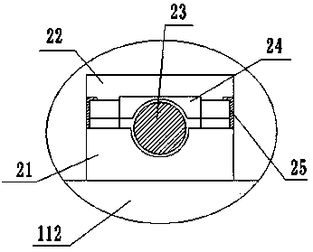
[0021] Such as figure 1 and figure 2 As shown in the present invention, a ball screw pair structure that can improve positioning accuracy, the ball screw pair includes a ball screw 1 body and a bearing 2 arranged in the ball screw 1 body, so The ball screw 1 body includes a screw shaft 11, a nut 12, a plurality of steel balls 13, a reverser 14 and a dust-proof valve 15, and the screw shaft 11 is composed of a rolling screw shaft 111 and a bearing shaft 112 A spiral outer raceway is provided on the outer peripheral surface of the rolling screw shaft 111; the nut 12 is sleeved on the rolling screw shaft 11, and the inner peripheral surface of the nut 12 is provided with the A spiral inner raceway that matches the outer raceway, and a circulating through hole 16 formed by connecting the two ends of the inner raceway in the nut 12 along its axial direction, wherein the inner raceway Formed at the position for the rolling of the steel balls; the plurality of steel balls 13 are a...
Embodiment 2
[0025] Such as image 3 and Figure 4As shown in the present invention, a ball screw pair structure that can improve positioning accuracy, the ball screw pair includes a ball screw 1 body and a bearing 2 arranged in the ball screw 1 body, so The ball screw 1 body includes a screw shaft 11, a nut 12, a plurality of steel balls 13, a reverser 14 and a dust-proof valve 15, and the screw shaft 11 is composed of a rolling screw shaft 111 and a bearing shaft 112 A spiral outer raceway is provided on the outer peripheral surface of the rolling screw shaft 111; the nut 12 is sleeved on the rolling screw shaft 11, and the inner peripheral surface of the nut 12 is provided with the A spiral inner raceway that matches the outer raceway, and a circulating through hole 16 formed by connecting the two ends of the inner raceway in the nut 12 along its axial direction, wherein the inner raceway Formed at the position for the rolling of the steel balls; the plurality of steel balls 13 are ar...
Embodiment 3
[0029] Such as Figure 5 and Figure 6 As shown in the present invention, a ball screw pair structure that can improve positioning accuracy, the ball screw pair includes a ball screw 1 body and a bearing 2 arranged in the ball screw 1 body, so The ball screw 1 body includes a screw shaft 11, a nut 12, a plurality of steel balls 13, a reverser 14 and a dust-proof valve 15, and the screw shaft 11 is composed of a rolling screw shaft 111 and a bearing shaft 112 A spiral outer raceway is provided on the outer peripheral surface of the rolling screw shaft 111; the nut 12 is sleeved on the rolling screw shaft 11, and the inner peripheral surface of the nut 12 is provided with the A spiral inner raceway that matches the outer raceway, and a circulating through hole 16 formed by connecting the two ends of the inner raceway in the nut 12 along its axial direction, wherein the inner raceway Formed at the position for the rolling of the steel balls; the plurality of steel balls 13 are ...
PUM
 Abstract
Description
Claims
Application Information
 - Generate Ideas
- Intellectual Property
- Life Sciences
- Materials
- Tech Scout
- Unparalleled Data Quality
- Higher Quality Content
- 60% Fewer Hallucinations
Browse by: Latest US Patents, China's latest patents, Technical Efficacy Thesaurus, Application Domain, Technology Topic, Popular Technical Reports.
© 2025 PatSnap. All rights reserved.Legal|Privacy policy|Modern Slavery Act Transparency Statement|Sitemap|About US| Contact US: help@patsnap.com


