Welding positioning machine for reinforcement cage

A welding positioner and reinforcement cage technology, applied in welding equipment, auxiliary welding equipment, welding/cutting auxiliary equipment, etc., can solve the problems of laborious rotation at the end of the main reinforcement, poor rotation, unbalanced force at the end, etc., to achieve improved The Effect of Stirrup Wrap Binding and Welding Efficiency

Inactive Publication Date: 2019-05-21
CHONGQING TECH & BUSINESS INST
View PDF7 Cites 2 Cited by
  • Summary
  • Abstract
  • Description
  • Claims
  • Application Information

AI Technical Summary

Problems solved by technology

However, the current large-diameter or / and super-long steel cages have a very large weight when welding, so it is required to rotate and feed the steel cages when the stirrups are wound and bound and welded (i.e. displacement motion) to achieve welding Welding is carried out along the circumferential direction and length direction of the reinforcement cage. However, the current welding positioner only adopts the traction and rotation drive of the head end of the main reinforcement when it moves the reinforcement cage, which results in laborious rotation of the tail end of the main reinforcement and poor rotatability. Unbalanced force at the end, serious deformation, not suitable for large diameter (1mm and above) or super long (20m and above) reinforcement cages in the welding requirements

Method used


Image

  • Welding positioning machine for reinforcement cage
  • Welding positioning machine for reinforcement cage
  • Welding positioning machine for reinforcement cage

Examples


Embodiment

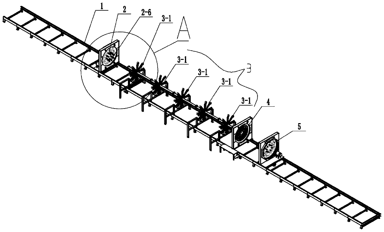
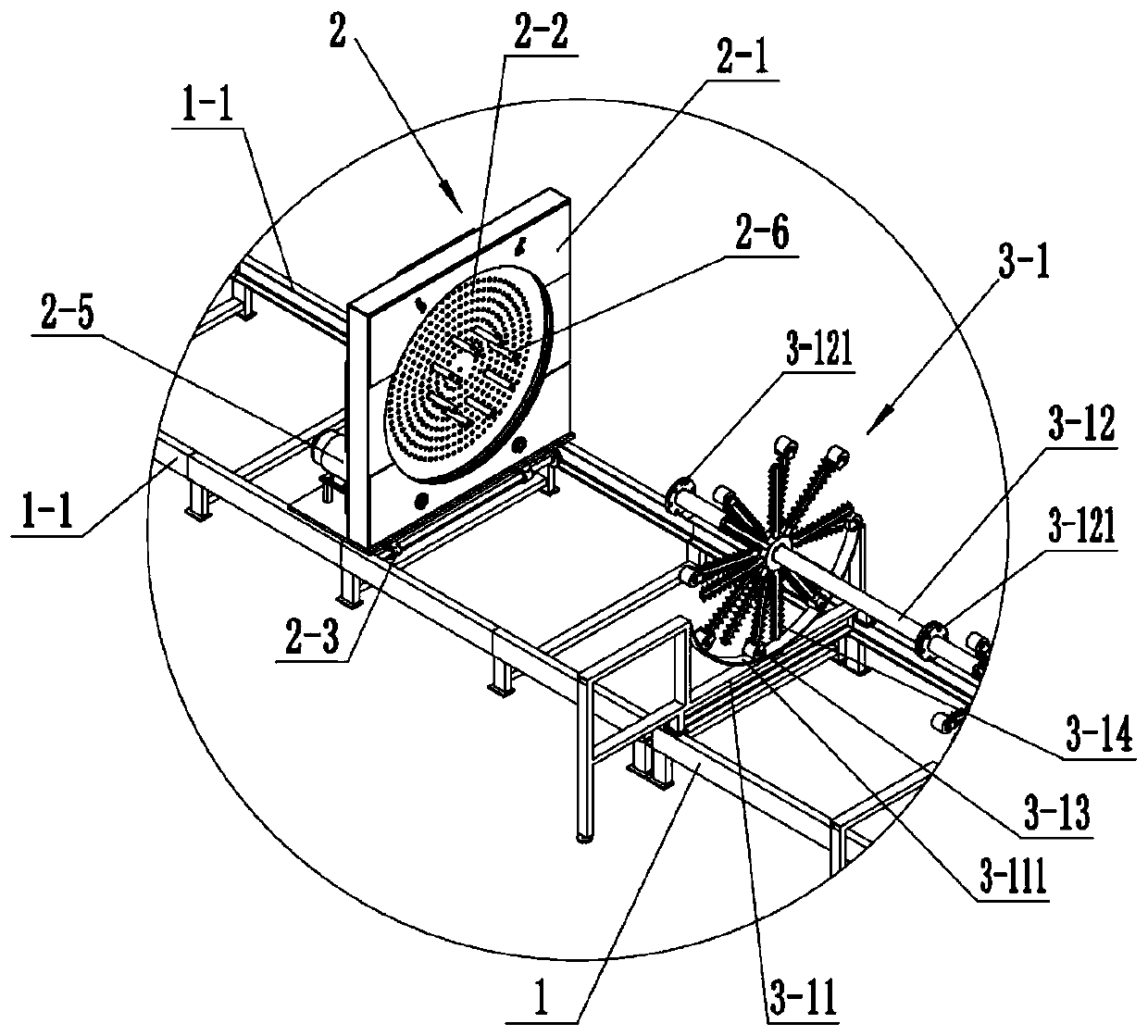
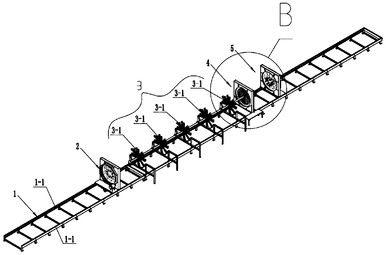
[0036] Example: see Figure 1-4 , a steel cage welding positioner, which includes a horizontal track 1, a main bar tail end traction rotation device 2, a main bar rotation support device 3, a main bar rotation positioning device 4 and a main bar head end traction rotation device 5.

[0037] Wherein, the tail-end traction and rotation device 2 of the main bars is used to drive the tail-ends of several main bars to be pulled forward to feed materials or / and drive the tail-ends of several main bars to perform circumferential rotation during steel cage welding.

[0038] Wherein, the main reinforcement rotating support device 3 is used for supporting the sections to be welded of each several main reinforcements when the reinforcement cage is welded, so as to prevent the displacement or deformation of several main reinforcements from affecting the stability of the shape and structure of the reinforcement cage. Rotation supporting device 3 can follow rotation.

[0039] Wherein, the ...


PUM


Abstract

The invention discloses a welding positioning machine for a reinforcement cage. The machine is characterized by comprising a horizontal rail (1), a main rib tail end pulling rotating device (2), a main rib rotating supporting device (3), a main rib rotating positioning device (4) and a main rib head end pulling rotating device (5), wherein the main rib tail end pulling rotating device (2), the main rib rotating supporting device (3), the main rib rotating positioning device (4) and the main rib head end pulling rotating device (5) are sequentially distributed in the direction of the horizontalrail (1). With the adoption of the machine, each main rib welding section can be rotated and positioned and axially pulled and automatically horizontally fed during coiling and binding stirrups and / or welding of the reinforcement cage, and both time and force can be saved; the stirrup coiling binding and welding efficiency can be greatly improved; and the machine is particularly applicable to coiling binding and welding of stirrups of large-diameter and / or super-long reinforcement cages.

Description

technical field [0001] The invention belongs to a steel cage welding positioner. Background technique [0002] The reinforcement cage is formed by welding the main reinforcement and the stirrup. The main reinforcement is spaced apart and parallel to form a circular (rectangular or oval, etc.) On the main muscle. However, the current large-diameter or / and super-long steel cage has a very large weight when welding, so it is required to rotate and feed the steel cage when the stirrup is wound and bound and welded (ie displacement movement) to achieve welding Welding is carried out along the circumferential direction and length direction of the steel cage. However, the current welding positioner only uses the traction and rotation drive for the head end of the main reinforcement when the steel cage is displaced, which results in laborious rotation of the tail end of the main reinforcement and poor rotatability. Unbalanced force at the end, serious deformation, not suitable for...

Claims


Application Information

Patent Timeline
IPC IPC(8): B23K37/047B21F31/00
Inventor 贺华刚
Owner CHONGQING TECH & BUSINESS INST
Why Eureka
Try Eureka