An Electromechanical Controlled Cross Optical Path 3D Camera

A technology of camera and optical path, which is applied in the field of 3D camera with electromechanical control crossed optical path, can solve the problems that the microscope does not have zoom and focus functions, and achieve the effect of comfortable observation and real and clear 3D images

Active Publication Date: 2021-06-11
濮阳市润源医用品有限公司
View PDF10 Cites 0 Cited by
  • Summary
  • Abstract
  • Description
  • Claims
  • Application Information

AI Technical Summary

Problems solved by technology

[0004] The purpose of the present invention is to provide a 3D camera with electromechanical control crossed optical paths, to solve the above-mentioned background technology, the pure optical surgical microscopes with small objective lens structure do not have zoom and focus functions, and the pupils only operate on the microscope eyepieces for a long time. It is an unbearable problem for ordinary people

Method used


Image

  • An Electromechanical Controlled Cross Optical Path 3D Camera
  • An Electromechanical Controlled Cross Optical Path 3D Camera
  • An Electromechanical Controlled Cross Optical Path 3D Camera

Examples


Embodiment 1

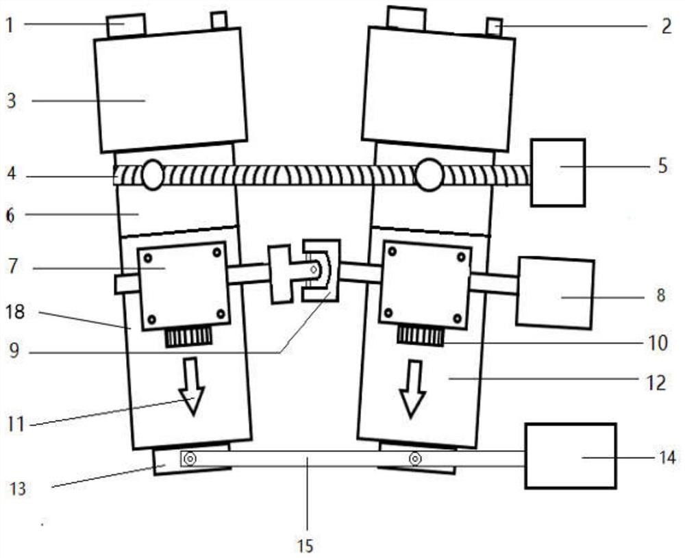
[0023] An electromechanical control cross optical path 3D camera, such as figure 1 As shown, it includes two lens barrels 18 installed in parallel, and the top of each lens barrel 18 is equipped with a photoelectronic sensor 3, and the top of the photoelectronic sensor 3 is provided with a photoelectronic sensor output port 1 and a photoelectronic sensor power input port 2, and the two mirrors The rotation adjustment ring of the outer wall of the tube 18 is connected by the variable visual cross linkage rod 4, one end of the variable visual cross linkage rod 4 is provided with the visual cross linkage power device 5, and the middle parts of the outer walls of the two lens barrels 18 are respectively provided with Steering gear 7, the bottom of each steering gear 7 is equipped with zoom gear 10, and the outer wall of two lens barrels 18 is also provided with guide laser light 11, two steering gears 7 are connected by zoom universal coupling 9, zoom universal A zoom power unit 8...

Embodiment 2

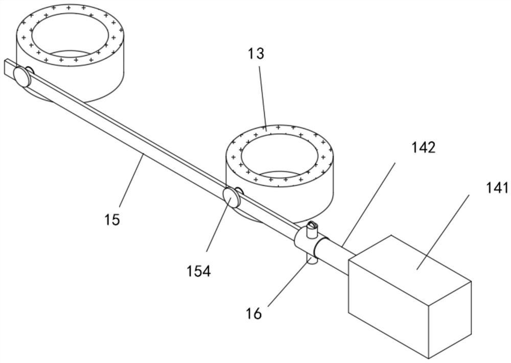
[0027] As a second embodiment of the present invention, such as figure 2 and image 3 As shown, the visual cross link power unit 5 , the zoom power unit 8 and the focus power unit 14 all include a cylinder 141 , and the cylinder 141 is provided with a piston rod 142 .

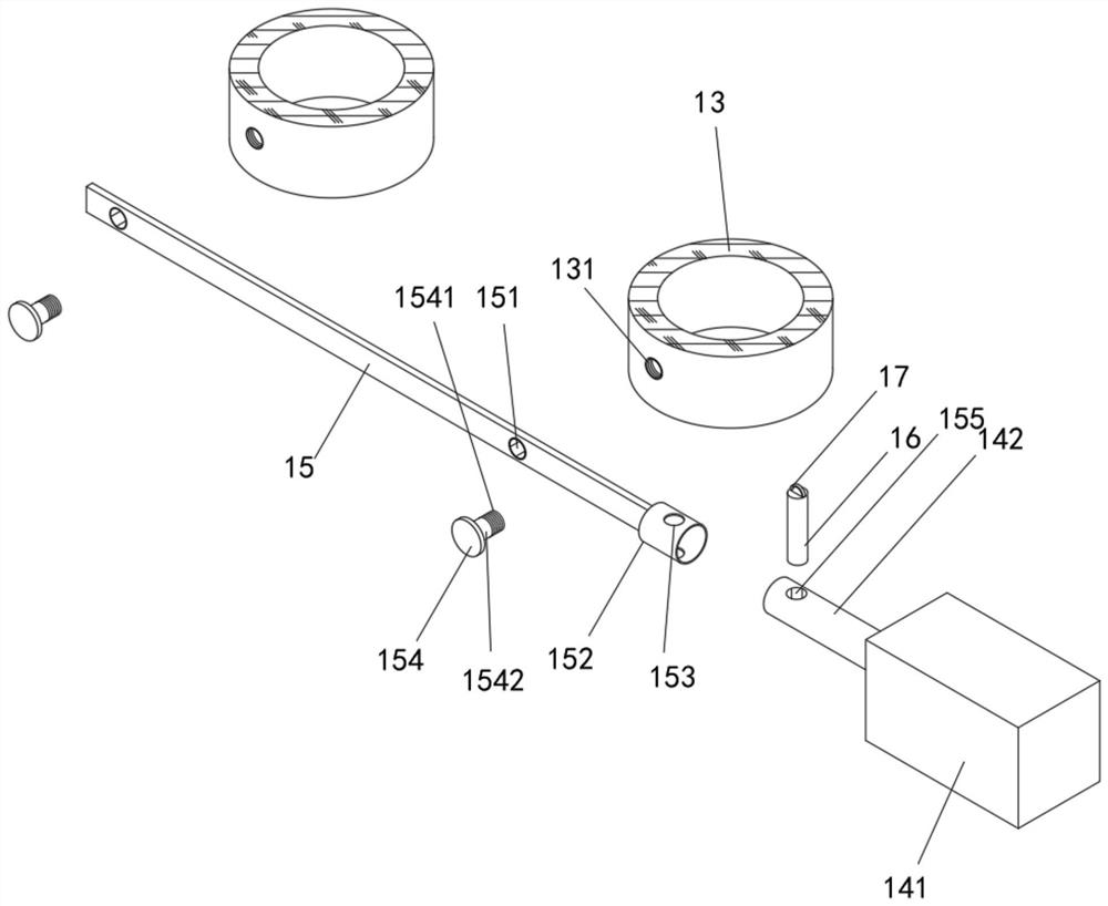
[0028] Further, two rotating holes 151 are provided on the focusing linkage rod 15, and the distance between the two rotating holes 151 is adapted to the distance between the two objective lenses 13. The focusing linkage rod 15 is close to the One end is provided with a fixed sleeve 152, the fixed sleeve 152 and the focusing linkage rod 15 are integrally formed, the fixed sleeve 152 is provided with a first fixed hole 153, the outer wall of the objective lens 13 is provided with a screw hole 131, and the piston rod A second fixing hole 155 is opened on the circumferential surface of the end of the cylinder 142 far away from the cylinder 141 , and the piston rod 142 is inserted into the fixing sleeve 152 .

...


PUM


Abstract

The invention relates to the technical field of mechanical equipment, in particular to a 3D camera head with electromechanical control crossing optical path, which includes two lens barrels installed in parallel. One end of the optic cross linkage rod is provided with an optic cross linkage power device, and the two steering gears are connected through a zoom universal coupling, and one end of the zoom universal coupling is connected with a zoom power device, and the two lens barrels An electronic eyepiece is installed on the top, and an objective lens is installed at the bottom of the two lens barrels. The two objective lenses are connected through a focusing linkage rod, and one end of the focusing linkage rod is connected with a focusing power device. The present invention does not need to use optical eyepieces, and the doctor can observe for a long time without staring at the optical port of the eyepieces, which makes the doctor more comfortable when observing. The matching devices and sensors are arranged coaxially and linearly to make the 3D images more real and clear.

Description

technical field [0001] The invention relates to the technical field of mechanical equipment, in particular to an electromechanical control cross optical path 3D camera. Background technique [0002] In order to perform the surgery accurately, an operating microscope is used to achieve 3D stereoscopic viewing. The principle of generating 3D stereo vision is that binocular vision comes from images in different directions on the left and right. 3D stereoscopic vision is formed through the visual integration of the brain. At present, the two optical tubes of surgical microscopes are generally installed in parallel. In order to make the two images overlap, a large objective lens is often used to refract and form a viewing angle. The structure is complex and has a certain impact on image quality. At present, there are also pure optical surgical microscopes with small objective lens structures, but without zoom and focus functions. Its structure is simple, only fixed working dis...

Claims


Application Information

Patent Timeline
Patent Type & Authority Patents(China)
IPC IPC(8): A61B90/20G02B21/36
Inventor 耿孟录
Owner 濮阳市润源医用品有限公司
Why Eureka
Try Eureka