Vehicle Micro Projector Display System
A micro-projector and display system technology, which is applied to instruments, vehicle components, optics, etc., can solve the problem of high cost, and achieve the effects of easy operation, simple implementation, and guaranteeing driving safety.
- Summary
- Abstract
- Description
- Claims
- Application Information
AI Technical Summary
Problems solved by technology
Method used
Image
Examples
Embodiment 1
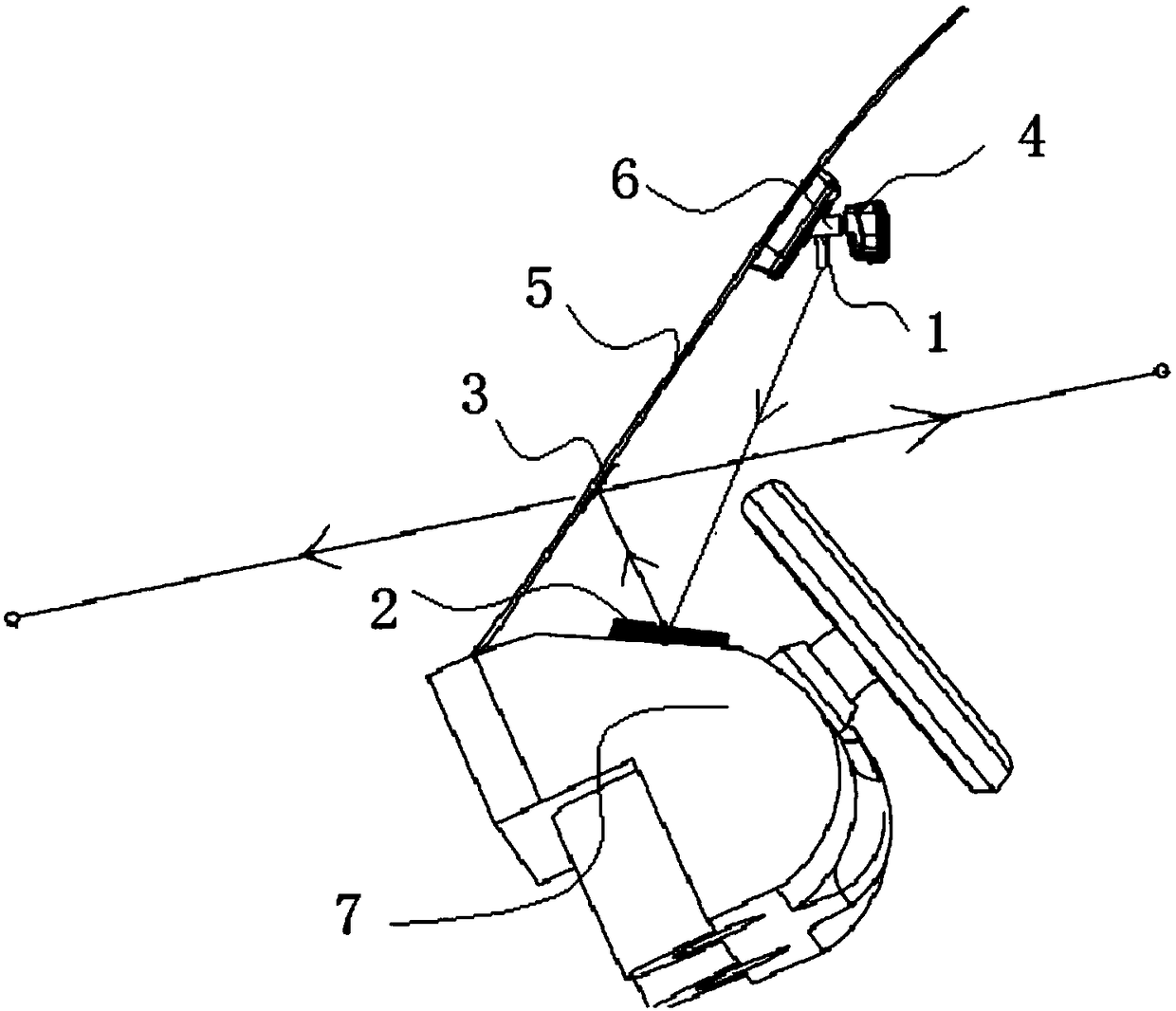
[0041] Please refer to figure 1 shown;
[0042] A vehicle-mounted micro-projector display system disclosed by the present invention includes a control terminal, a signal receiving module, a signal processing module, a laser head 1, a first reflector 2 and a semi-transparent reflective film 3;
[0043] The control terminal is used to send an image signal to the signal processing module; the control terminal of this embodiment can adopt a smart phone, a smart navigator, a computer, an IPAD and a smart vehicle system;
[0044] The signal receiving module is used to connect the control terminal and the signal processing module, and transmit the control image signals output by the control terminals such as smart phones, smart navigators, computers and smart vehicle systems to the signal processing module;
[0045] The current general signal transmission method can be used for signal transmission between the signal receiving module and the control terminal. Preferably, the signal r...
Embodiment 2
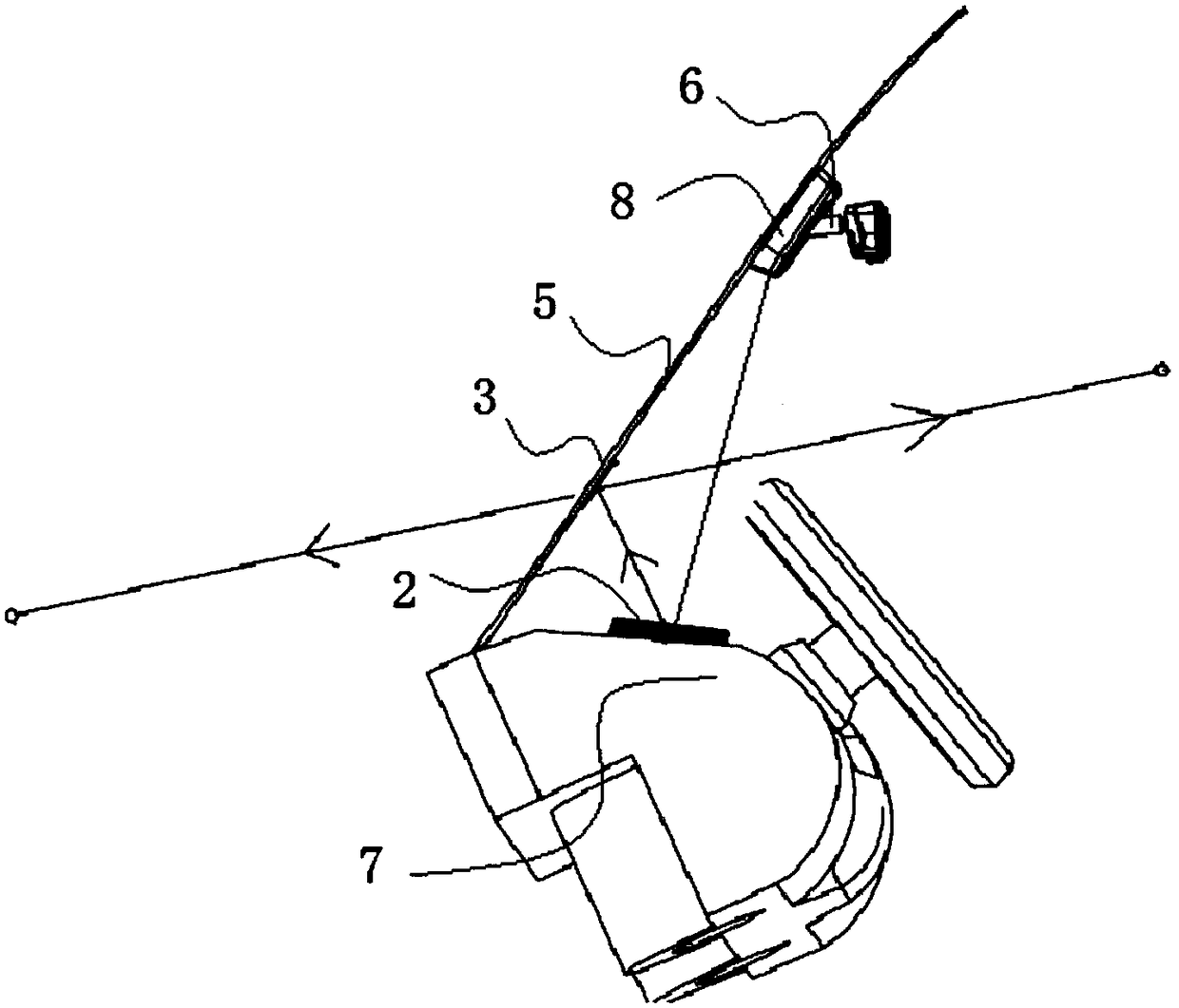
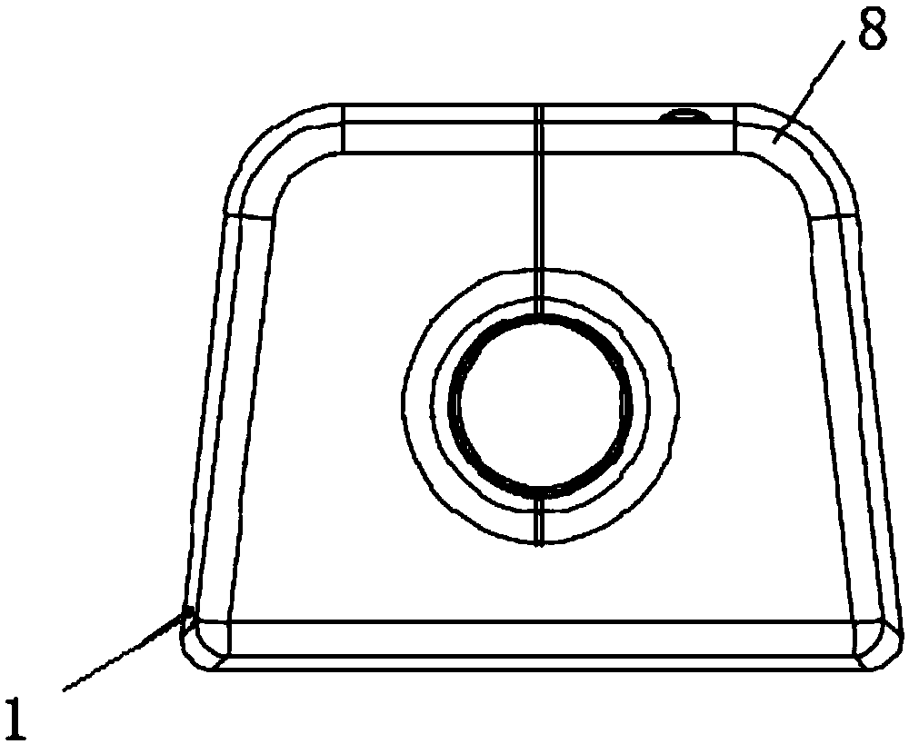
[0053] Please refer to figure 2 and image 3 shown;
[0054] A vehicle-mounted micro-projector display system disclosed by the present invention includes a control terminal, a signal receiving module, a signal processing module, a laser head 1, a first reflector 2 and a semi-transparent reflective film 3;
[0055] The control terminal is used to send an image signal to the signal processing module; the control terminal of this embodiment can adopt a smart phone, a smart navigator, a computer, an IPAD and a smart vehicle system;
[0056] The signal receiving module is used to connect the control terminal and the signal processing module, and transmit the control image signals output by the control terminals such as smart phones, smart navigators, computers and smart vehicle systems to the signal processing module;
[0057] The current general signal transmission method can be used for signal transmission between the signal receiving module and the control terminal. Preferabl...
Embodiment 3
[0065] Please refer to Figure 4-Figure 6 shown;
[0066] A vehicle-mounted micro-projector display system disclosed by the present invention includes a control terminal, a signal receiving module, a signal processing module, a laser head 1, a first reflector 2 and a semi-transparent reflective film 3;
[0067] The control terminal is used to send an image signal to the signal processing module; the control terminal of this embodiment can adopt a smart phone, a smart navigator, a computer, an IPAD and a smart vehicle system;
[0068] The signal receiving module is used to connect the control terminal and the signal processing module, and transmit the control image signals output by the control terminals such as smart phones, smart navigators, computers and smart vehicle systems to the signal processing module;
[0069] The current general signal transmission method can be used for signal transmission between the signal receiving module and the control terminal. Preferably, th...
PUM
 Abstract
Description
Claims
Application Information
 - R&D
- Intellectual Property
- Life Sciences
- Materials
- Tech Scout
- Unparalleled Data Quality
- Higher Quality Content
- 60% Fewer Hallucinations
Browse by: Latest US Patents, China's latest patents, Technical Efficacy Thesaurus, Application Domain, Technology Topic, Popular Technical Reports.
© 2025 PatSnap. All rights reserved.Legal|Privacy policy|Modern Slavery Act Transparency Statement|Sitemap|About US| Contact US: help@patsnap.com


