
Wiring terminal

A technology of terminals and pins, applied in the direction of connection, contact parts, parts of connection devices, etc., can solve the problems of wiring damage, cumbersome operation process, time-consuming and labor-intensive, etc.

Inactive Publication Date: 2019-05-17
GUIZHOU RUIXIN TECH
View PDF6 Cites 0 Cited by
  • Summary
  • Abstract
  • Description
  • Claims
  • Application Information

AI Technical Summary

Problems solved by technology

[0003] At present, the commonly used wiring terminals mainly include an insulating shell with a wiring hole, and a conductive sheet inside the insulating shell. One end of the conductive sheet penetrates the insulating shell and extends to the outside of the insulating shell, and the other end of the conductive sheet is located in the wiring hole. , There is also a crimping hole on the insulating shell, the crimping hole is connected with the wiring hole, and the inner thread of the crimping hole is connected with a screw. During use, first insert the wiring into the wiring hole and make contact with the conductive sheet, and then screw it tightly. The rod can be used to compress the wiring, but there are the following problems in this wiring method: the tightness of the wiring is controlled by controlling the screwing in and out of the pressing rod, and the operation process is cumbersome and time-consuming. After being in contact with the wiring, the operator needs to rely on his own experience to judge whether the wiring is compressed by the compression rod. If the wiring is already compressed and then continue to twist the compression rod, it will cause damage to the wiring

Method used


Image

  • Wiring terminal
  • Wiring terminal

Examples


Embodiment Construction

[0018] The following is further described in detail through specific implementation methods:

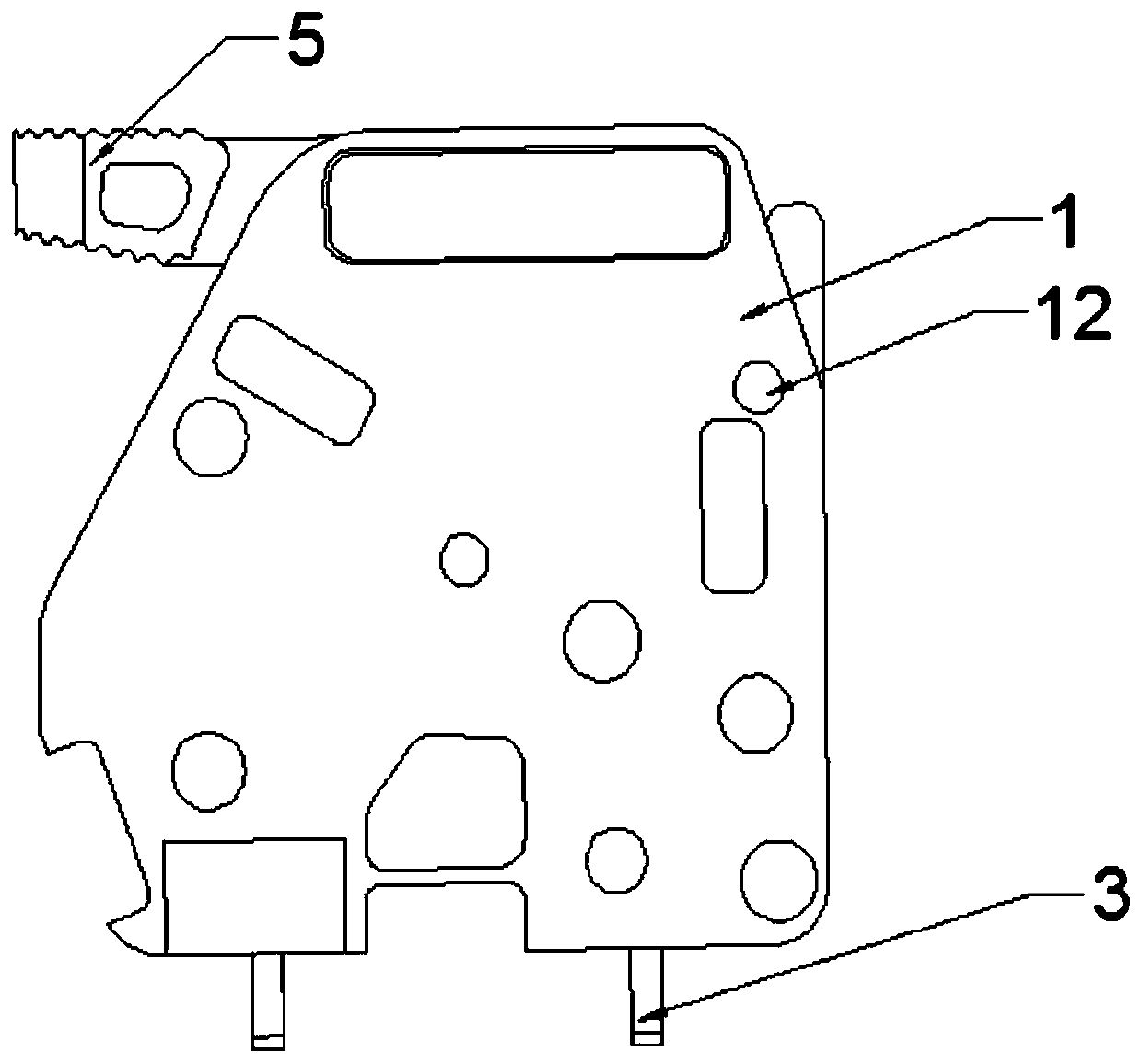
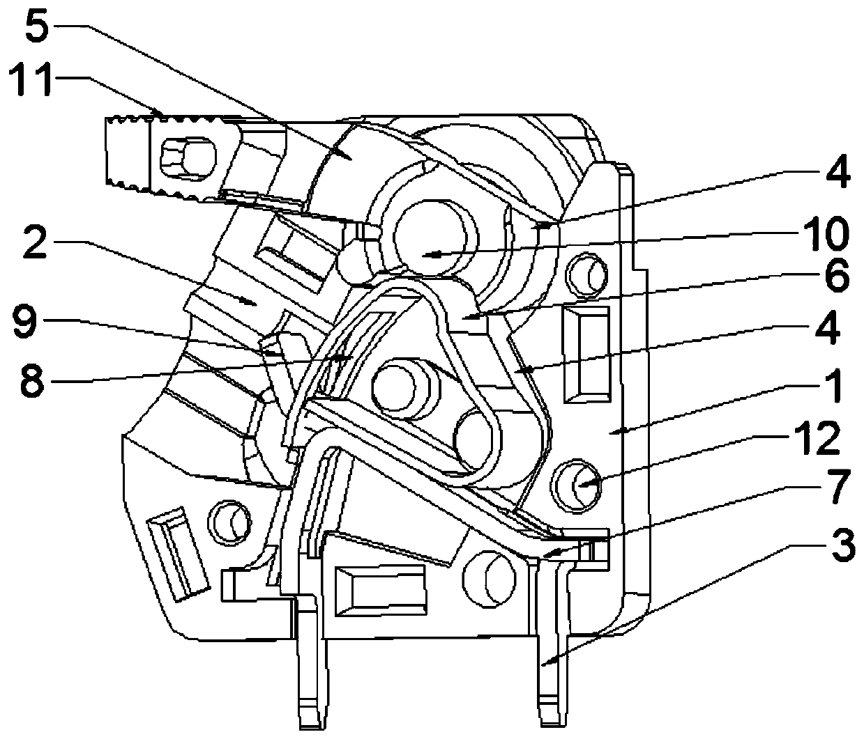
[0019] The reference signs in the drawings of the description include: insulating shell 1, wiring hole 2, wiring pin 3, cam 4, handle 5, ring spring 6, L-shaped spring 7, bar-shaped hole 8, clamping elbow 9, cylindrical pin 10. Anti-slip pattern 11. Cooling holes 12.

[0020] The embodiment is basically as attached figure 1 And attached figure 2 Shown:

[0021] A connection terminal, comprising two insulating shells 1 that are fastened to each other and a switching mechanism disposed inside the insulating shell 1, the insulating shell 1 is provided with an inner cavity for placing the switching mechanism, and one side of the insulating shell 1 is provided with a wiring hole 2 , the other side is provided with a terminal pin 3 extending out of the insulating shell 1, the switching mechanism includes a conductive piece with elasticity and a cam 4 for pressing the conductive piece, ...


PUM


Abstract

The invention discloses a wiring terminal in the field of electrical part equipment. The wiring terminal comprises two insulation shells and changeover mechanisms, wherein the two insulation shells are buckled with each other, the changeover mechanisms are arranged in the insulation shells, inner cavities are formed in the insulation shells and are used for placing the changeover mechanisms, a wiring hole is formed in one side of each insulation shell, a wiring pin is arranged at the other side of the insulation shell and extends out of the insulation shell, each changeover mechanism comprisesan elastic conductive sheet and a cam, the cam is used for extruding the conductive sheet, one end of the conductive sheet is fixed with the wiring pin, the cam is hinged with the insulation shell and props against the conductive sheet, a handle is fixedly connected with the cam, and a range-limitation hole is formed in the insulation shell and is used for the handle to penetrate through and freely rotate. When the wiring terminal disclosed by the scheme is used for wiring, wiring is more convenient and is labor-saving, and the damage degree of wiring is reduced.

Description

technical field [0001] The invention belongs to the field of electric accessory equipment, and in particular relates to a connection terminal. Background technique [0002] The terminal is the part that connects the battery to the external conductor. In electrotechnical science, the terminal refers to the terminal, also known as the terminal. copper, aluminum and iron etc. Their function is mainly to transmit electrical signals or to conduct electricity. Terminal blocks are gradually widely used in various fields, and play a connection role in transmitting electrical signals and conducting electricity, thereby reducing the workload and consumption of production costs, bringing a lot of convenience to production and use, and avoiding many troubles. Thereby, the purpose of simplifying the product structure and saving the manufacturing cost is achieved. Therefore, based on the benefits brought by terminal testing and combined with market analysis, it is recommended that inst...

Claims


Application Information

Patent Timeline
IPC IPC(8): H01R4/18H01R13/187H01R13/193H01R13/24H01R13/502H01R13/629H01R13/639
Inventor 温小远
Owner GUIZHOU RUIXIN TECH
Learn More