A mapping method for fine characterization of sedimentary facies

A technique of sedimentary facies and mapping, applied in the fields of seismology and seismic signal processing for well logging records, can solve the problem of inability to accurately predict the spatial distribution shape and scale of reservoirs, and fail to meet the needs of fine interpretation of reservoir internal structure , It is difficult to meet the problems of potential tapping and well location deployment, so as to achieve the effect of improving seismic resolution, facilitating operation and improving the use accuracy

Active Publication Date: 2020-06-30
CHINA NATIONAL OFFSHORE OIL (CHINA) CO LTD +1
View PDF7 Cites 1 Cited by
  • Summary
  • Abstract
  • Description
  • Claims
  • Application Information

AI Technical Summary

Problems solved by technology

However, due to the restriction of seismic data resolution and the diachronism of lithological interfaces, the traditional seismic facies analysis method cannot meet the needs of fine interpretation of reservoir internal structure in reservoir development geological research.
For the sedimentary facies characterization of well information, multi-well information is used to compile sedimentary facies maps. This method cannot realize the prediction of sand bodies between well locations, and can only use interpolation, which cannot accurately predict the spatial distribution and scale of reservoirs. Meet the needs of remaining oil potential tapping and well location deployment in the middle and later stages of oilfield development

Method used


Image

  • A mapping method for fine characterization of sedimentary facies
  • A mapping method for fine characterization of sedimentary facies
  • A mapping method for fine characterization of sedimentary facies

Examples


Embodiment Construction

[0027] The experimental methods used in the following examples are conventional methods unless otherwise specified.

[0028] The present invention will be described in detail below in conjunction with the accompanying drawings and examples.

[0029] Figure 1~ image 3 As shown, the method for forming a map of sedimentary facies fine characterization of the present invention comprises the following steps:

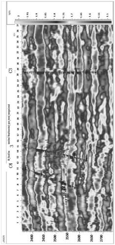
[0030] 1) As shown in Fig. 1, the plane map of seismic attributes of a certain target reservoir. The seismic section shows a seismic reflection axis, the formation thickness is thick, the reservoir thickness is about 30-50m, and the sedimentary facies map is too thick to meet the needs of well location adjustment.

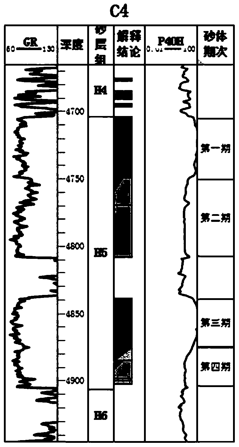
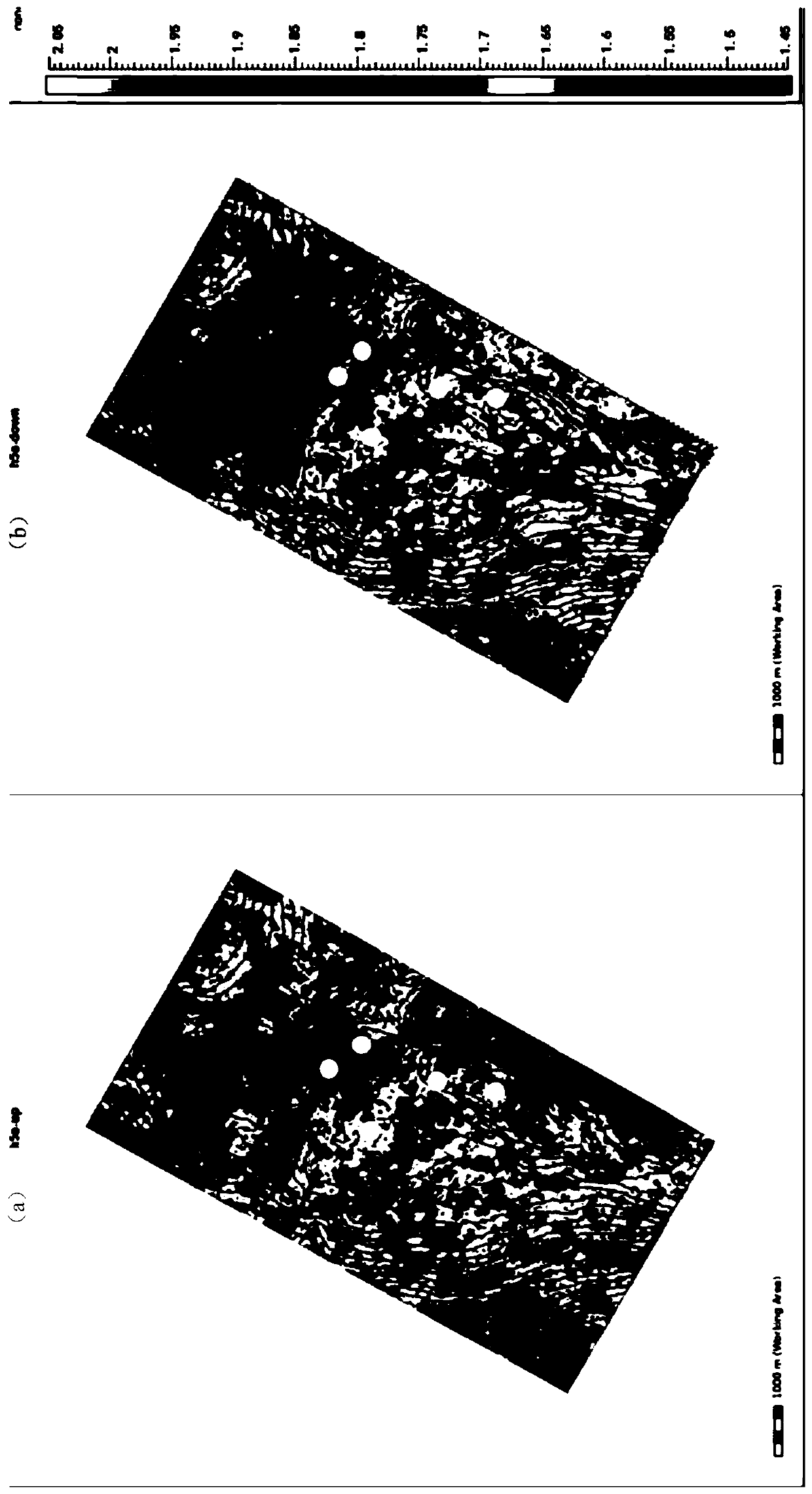
[0031] 2) Divide the reservoir stages on the well, and obtain the thickness ratio plan of each stage, as shown in Figure 2 ~ Figure 3 shown.

[0032] Due to the cyclic nature of deposition, although there are phase transitions at different well points, each ...


PUM


Abstract

The invention discloses a mapping method for a sedimentary facies meticulous depiction. The mapping method comprises the following steps that a coarse sedimentary facies plan is formed on a seismic profile to extract seismic attributes according to a seismic reflection axis for a target reservoirstratum; each sedimentary stage is identified according to sedimentary characteristics and logging morphologies at a well point, and the ratio of the each sedimentary stage to actual drilling is calculated throughthe sedimentary characteristics and the logging morphologies; the ratio of the plane thickness of the each sedimentary stage is obtained by an interpolation amongwells of the target reservoir stratum using the ratio of the actual drilling, the seismic axis is split, the seismic attributesare extracted, and the division of the coarse sedimentary facies plan on the vertical reservoir stratum is achieved according to the ratio of the each sedimentary stage; and the seismic attributes ofthe each sedimentary stageare extracted from the distribution status on the profile and on a plane,sedimentary facies of each seismic attribute are depicted, a plurality ofthe sedimentary facies are carved out, and the subdivision map of the sedimentary facies is obtained. The mapping method for the sedimentary facies meticulous depiction is the sedimentary facies meticulous depiction with the sparse well pattern density and the lower seismic resolution, and can be applied tothe oil field of exploration and development.

Description

technical field [0001] The invention relates to a mapping method for finely depicting sedimentary facies, belonging to the field of oil and gas exploitation. Background technique [0002] A fine sedimentary facies plan is an important basis for oilfield production planning, dynamic analysis and adjustment of the development process. Due to the cyclic nature of the sedimentary body, the lateral phase change of the sedimentary facies belt is large and the internal structure is complex, which inevitably requires the fine characterization of the sedimentary facies from the vertical and plane, so as to accurately improve the well location deployment and deep excavation of the remaining Oil and avoid problems such as rising water content. At present, the description of fine sedimentary facies is mainly based on 3D seismic information and well information. However, due to the limitation of seismic data resolution and the diachronism of lithological interface, the traditional seis...

Claims


Application Information

Patent Timeline
Patent Type & Authority Patents(China)
IPC IPC(8): G01V1/50
Inventor 陈飞范廷恩胡光义范洪军王宗俊赵卫平高云峰田楠董洪超解超余连勇樊鹏军马良涛商志垒
Owner CHINA NATIONAL OFFSHORE OIL (CHINA) CO LTD
Why Eureka
Try Eureka