
Device for electromagnetic compatible radiation immunity test of electronic thermometer

An electronic thermometer, radiation immunity technology, applied in the direction of thermometer testing/calibration, thermometers, measuring devices, etc., can solve the problem of inability to observe the working conditions and measurement accuracy of electronic thermometers, difficult for electronic thermometers to work continuously, and inability to display real-time temperature and other problems, to achieve the effect of convenient multiple measurements, satisfying testing and monitoring, and beautiful appearance

Pending Publication Date: 2019-05-17
广东省医疗器械质量监督检验所
View PDF0 Cites 0 Cited by
  • Summary
  • Abstract
  • Description
  • Claims
  • Application Information

AI Technical Summary

Problems solved by technology

At present, in the radio frequency electromagnetic field radiation immunity test in the anechoic chamber, it is difficult to ensure that the electronic thermometer continues to work, and the working conditions and measurement accuracy of the electronic thermometer cannot be observed throughout the radio frequency electromagnetic field radiation immunity test, which is not conducive to judging the test result
On the one hand, electronic thermometers usually display a temperature range of 32°C to 43°C. Beyond this range, the real-time temperature cannot be displayed, low or high is displayed, and the electronic thermometer is turned on to measure the temperature. If the temperature measured by the electronic thermometer is constant at a maximum value for a period of time, this time Generally, it is 15s~20s, then the electronic thermometer will automatically shut down; on the other hand, the radio frequency electromagnetic field radiation immunity test of the electronic thermometer is tested in an anechoic chamber with a level of 3V / m, and the test staff cannot be exposed to operating electronic devices in the anechoic chamber. thermometer

Method used


Image

  • Device for electromagnetic compatible radiation immunity test of electronic thermometer
  • Device for electromagnetic compatible radiation immunity test of electronic thermometer

Examples


Embodiment

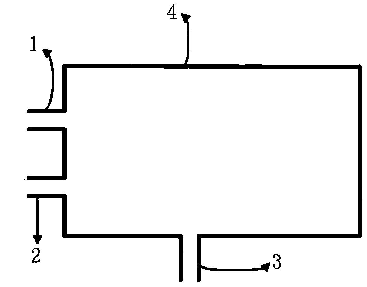
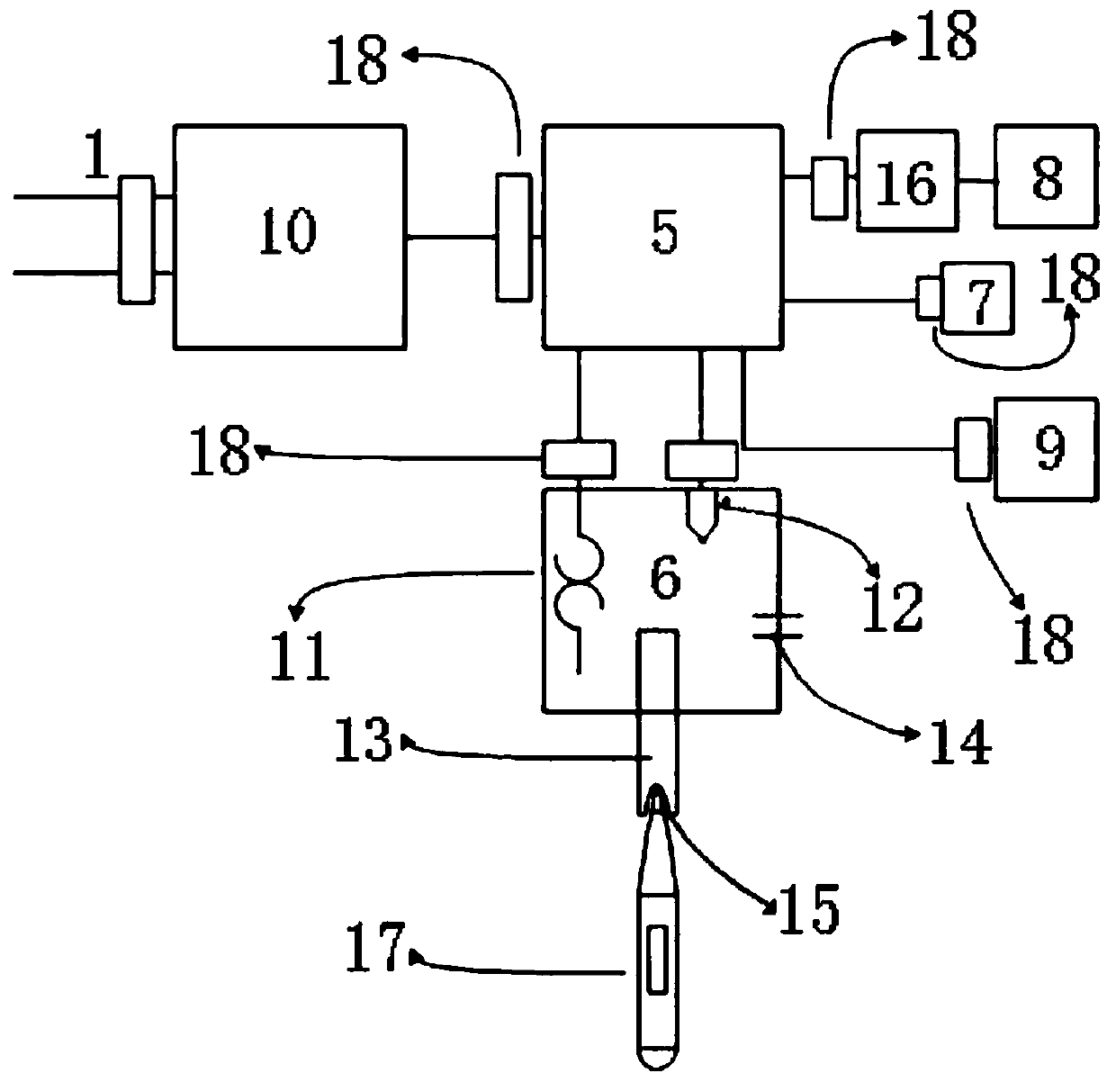
[0028] Such as figure 1 As shown, this embodiment discloses a device for the electromagnetic compatibility radiation immunity test of an electronic thermometer, which includes a packaging shell 4 and an internal structure. The heat pipe outlet 3, the internal structure includes a control module 5, a hot water tank 6, an input module for regulating the maximum heating temperature of the hot water tank, an output module for displaying the real-time temperature of the hot water tank, the hot water tank 6, Both the input module and the output module are electrically connected to the control module. Specifically, in this embodiment, the input module is a temperature selection knob 7, the output module is an LED display 8, an opening for installing the LED display 8 is opened on the packaging shell, and the control module 5 is a single-chip microcomputer.

[0029] The device used for the electromagnetic compatibility radiation immunity test of the electronic thermometer described i...


PUM


Abstract

The invention relates to the technical field of electromagnetic compatible tests, and discloses a device for the electromagnetic compatible radiation immunity test of an electronic thermometer. The device comprises an encapsulation shell and an internal structure; a device power port, a water changing hole of a water tank and a hot pipe outlet are arranged on the encapsulation shell; the internalstructure comprises a control module, a hot water tank, an input module and an output module; the input module is used for adjusting the highest heating temperature of the hot water tank; the output module is used for displaying the real-time temperature of the hot water tank; and the hot water tank, the input module and the output module are electrically connected with the control module. The device for the electromagnetic compatible radiation immunity test of the electronic thermometer in the invention can be used for monitoring and displaying in real time; the ascending speed is steady; andthe device has the advantages of being safe to use, convenient to operate and the like.

Description

technical field [0001] The invention relates to the technical field of electromagnetic compatibility testing, in particular to a device for an electronic thermometer electromagnetic compatibility radiation immunity test. Background technique [0002] With the development of science and technology, electronic technology is gradually developing towards high frequency, high speed, high precision, high reliability, high sensitivity, and high integration. Attaching great importance to it, more and more EMC directives, norms and standards are gradually promulgated and required to be enforced. Electromagnetic compatibility refers to the ability of a device or system to operate satisfactorily in its electromagnetic environment without causing intolerable electromagnetic interference to any device in its environment. Therefore, electromagnetic compatibility includes two requirements: on the one hand, it means that the electromagnetic interference generated by the equipment in the en...

Claims


Application Information

Patent Timeline
Patent Type & Authority Applications(China)
IPC IPC(8): G01R31/00G01K15/00G01R1/04
Inventor 伍倚明曾令优郑毅李伟松王仁礼曾俏
Owner 广东省医疗器械质量监督检验所
Learn More