A strip shape control method for dynamically changing strip width in cold tandem mill
A technology of dynamically changing specifications and shape control, which is applied in the field of steel rolling, can solve problems such as strip shape deterioration, reduce effective operation time, and dynamically change specifications, so as to improve the ability to adjust the shape online, increase the slab ratio of the unit, and design reasonable effect
- Summary
- Abstract
- Description
- Claims
- Application Information
AI Technical Summary
Problems solved by technology
Method used
Image
Examples
Embodiment 1
[0063] The front rolled steel width 1000mm → the rear ribbon steel width 1250mm ("Narrow-wide" dynamic variations):
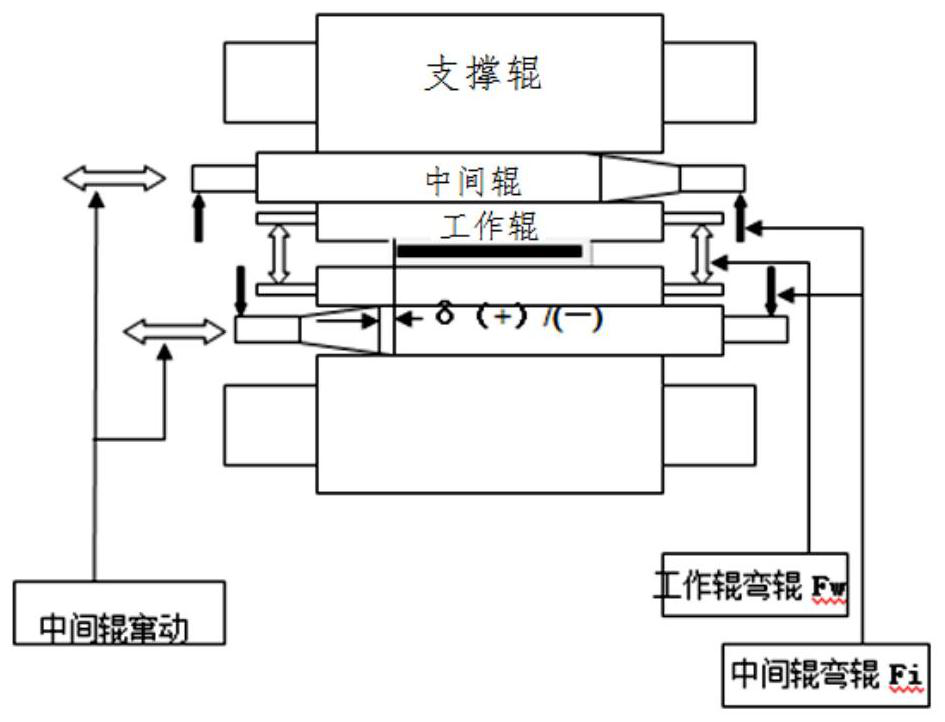
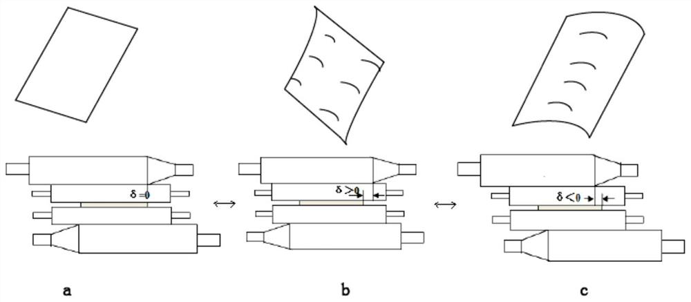
[0064] Through L = LM-B / 2-50 (in the form of: LM-traverse hydraulic cylinder limiting length, different coil units are different from the length of the working roll roll, and the selected intermediate roller transverse fluid cylinder model is different. Different, B-belt steel width; 50-steel side and intermediate roller roller end portions of the end portion of the intermediate roller roller body, different linking units also have a set change) Intermediate roller transverse hydraulic cylinder stroke calculation formula calculation, intermediate Roller swift transmissive hydraulic cylinder stroke L: (lm = 837.5mm)
[0065] Previous volume L before = 837.5-1000 / 2-50 = 287.5mm
[0066] After the latter volume L is = 837.5-1250 / 2-50 = 162.5mm
[0067] Pre-pre-roller 1 / 2 l = l - (1 Pre-l) / 2=287.5- (287.5-162.5) / 2 = 225mm
[0068]
Embodiment 2
[0070] The front rolled steel width 1219mm → the rear ribbon steel width is 1500mm ("narrow width" dynamic variations):
[0071] Through L = LM-B / 2-50 (in the form of: LM-traverse hydraulic cylinder limiting length, different coil units are different from the length of the working roll roll, and the selected intermediate roller transverse fluid cylinder model is different. Different, B-belt steel width; 50-steel side and intermediate roller roller end portions of the end portion of the intermediate roller roller body, different linking units also have a set change) Intermediate roller transverse hydraulic cylinder stroke calculation formula calculation, intermediate Roller swift transmissive hydraulic cylinder stroke L: (lm = 837.5mm)
[0072] Previous volume L before = 837.5-1219 / 2-50 = 178mm
[0073] The latter volume l after = 837.5-1500 / 2-50 = 37.5mm
[0074] Pre-pre-roller 1 / 2 l = l - (1 before -L) / 2 = 178- (178-37.5) / 2=107.75mm ≈ 108mm
[0075]
[0076] Further, ...
Embodiment 3
[0083] The front rolled steel width 1250mm → the rear ribbon steel width 1000mm ("wide narrow" dynamic variation):
[0084] Through L = LM-B / 2-50 (in the form of: LM-traverse hydraulic cylinder limiting length, different coil units are different from the length of the working roll roll, and the selected intermediate roller transverse fluid cylinder model is different. Different, B-belt steel width; 50-steel side and intermediate roller roller end portions of the end portion of the intermediate roller roller body, different linking units also have a set change) Intermediate roller transverse hydraulic cylinder stroke calculation formula calculation, intermediate Roller swift transmissive hydraulic cylinder stroke L: (lm = 837.5mm)
[0085] Previous volume L before = 837.5-1250 / 2-50 = 162.5mm
[0086] The latter volume l after = 837.5-1000 / 2-50 = 287.5mm
[0087] Pre-pre-roller 1 / 2 L = l + (L-L before-l) / 2=162.5+ (287.5-162.5) / 2 = 225mm
[0088]
PUM
 Abstract
Description
Claims
Application Information
 - Generate Ideas
- Intellectual Property
- Life Sciences
- Materials
- Tech Scout
- Unparalleled Data Quality
- Higher Quality Content
- 60% Fewer Hallucinations
Browse by: Latest US Patents, China's latest patents, Technical Efficacy Thesaurus, Application Domain, Technology Topic, Popular Technical Reports.
© 2025 PatSnap. All rights reserved.Legal|Privacy policy|Modern Slavery Act Transparency Statement|Sitemap|About US| Contact US: help@patsnap.com


