An optical fiber probe type cleaning and detection system and its production and use method
An optical fiber probe and cleaning technology, which is applied in cleaning methods and appliances, cleaning methods using liquids, chemical instruments and methods, etc., can solve the problems that cleaning technology cannot go deep into the inside of equipment and clean dead angles, so as to reduce manufacturing costs and difficulty in use , easy operation, high integration effect
- Summary
- Abstract
- Description
- Claims
- Application Information
AI Technical Summary
Problems solved by technology
Method used
Image


Examples
Embodiment 1
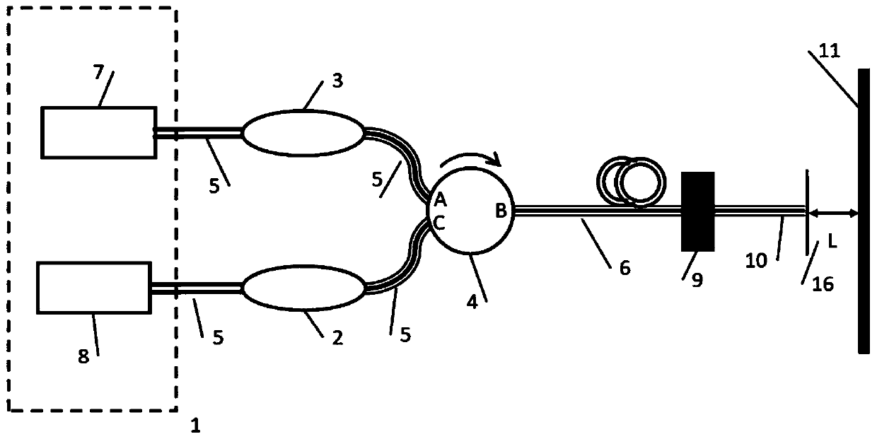
[0038] like Figure 1 to Figure 6 As shown, a kind of optical fiber probe type cleaning of the present invention, detection system, comprises spectrum analyzer 1 and circulator 4, and described spectrum analyzer 1 comprises laser 7 and spectrometer 8, and described laser 7 is the broadband light source of 1505 to 1630nm , the output optical power is 0 to 6dBm; the spectrometer 8 is a multi-port optical power analyzer, the detectable wavelength range is 1505 to 1630nm, and the detectable power range is -80dBm to 10dBm.
[0039] The circulator 4 is a three-port unidirectional ring device, the circulator 4 includes an A port, a B port and a C port, and the optical signal can only be transmitted in one direction in the circulator 4, that is, the optical signal can only be transmitted along the A port To the B port, and then transmitted from the B port to the C port, and the C port is then transmitted to the A port, and the reverse direction is isolated.
[0040] Two front-section...
Embodiment 2
[0047] like figure 1 Described, a method for manufacturing an optical fiber probe type cleaning and detection system, comprising the following steps:
[0048] a) Connect the output end of the laser 7 to one end of the amplifier 3 to amplify the optical signal to realize the adjustable 0-300mw;
[0049] b) The A port of the circulator 4 is connected to the other end of the amplifier 3, and the B port is connected to the rear single-mode fiber 6;
[0050] c) Select a point on the single-mode optical fiber 6 in the rear section, fix it on the displacement table 9, and cut the end face of the single-mode optical fiber 6 in the rear section flat to form an optical fiber probe;
[0051] d) One end of the attenuator 2 is connected to the C port of the circulator 4, and the other end is connected to the spectrometer 8. The attenuator 2 attenuates the optical power to below the safe power of the spectrometer 8.
Embodiment 3
[0053] like Figure 1 to Figure 6 As shown, a method for using an optical fiber probe cleaning and detection system specifically includes the following steps:
[0054] Step 1: Immerse the surface to be cleaned 11 in the liquid, adjust the displacement table 9, so that the length L of the working chamber 16 is about 24-200 μm;
[0055] Step 2: Turn on the laser 1, adjust the displacement stage 9, move the fiber probe 10, and observe the interference signal on the spectrometer 8: if the interference signal is smooth, it indicates that the surface 11 to be cleaned is the clean surface; if the interference signal is not smooth, It is necessary to clean the cleaning surface 11 and fix the displacement stage 9;
[0056] Step 3: Slowly adjust the amplifier 3 to gradually increase the optical power until bubbles 12 are generated in the working cavity 16, such as Figure 4 As shown, the system enters the overall cleaning mode. The generation rate of bubbles can be controlled by adju...
PUM
| Property | Measurement | Unit |
|---|---|---|
| diameter | aaaaa | aaaaa |
| diameter | aaaaa | aaaaa |
| wavelength | aaaaa | aaaaa |
Abstract
Description
Claims
Application Information
 - R&D
- Intellectual Property
- Life Sciences
- Materials
- Tech Scout
- Unparalleled Data Quality
- Higher Quality Content
- 60% Fewer Hallucinations
Browse by: Latest US Patents, China's latest patents, Technical Efficacy Thesaurus, Application Domain, Technology Topic, Popular Technical Reports.
© 2025 PatSnap. All rights reserved.Legal|Privacy policy|Modern Slavery Act Transparency Statement|Sitemap|About US| Contact US: help@patsnap.com