
Rail grinding trolley

A technology for grinding trolleys and rails, which is applied in the direction of track, track laying, track maintenance, etc. It can solve problems such as affecting the quality of grinding, derailment of small curves, difficulties, etc., to achieve precise control and self-locking, avoiding derailment in curved directions, and improving The effect of grinding quality

Pending Publication Date: 2019-05-14
长沙瀚鹏电子技术有限公司
View PDF0 Cites 12 Cited by
  • Summary
  • Abstract
  • Description
  • Claims
  • Application Information

AI Technical Summary

Problems solved by technology

[0004] The object of the present invention is to provide a rail grinding trolley to solve the problem that the traction structure of the grinding vehicle proposed in the above background technology is easy to run in the reverse direction, which not only affects the grinding quality, but also easily causes the small curve of the car to derail, and the grinding unit is controlled by the oil cylinder. When deflecting, the oil cylinder is prone to internal leakage, which makes it difficult to self-lock the angle, and the grinding unit cannot move laterally, and it is easy to touch obstacles such as axle counters when working on small curves and turnouts, and there is no derailment protection device, or the derailment protection device and the rail are sliding Friction, when the grinding car derails under special circumstances, the problem of often scratching the rails

Method used


Image

  • Rail grinding trolley
  • Rail grinding trolley
  • Rail grinding trolley

Examples


Embodiment Construction

[0018] The following will clearly and completely describe the technical solutions in the embodiments of the present invention with reference to the accompanying drawings in the embodiments of the present invention. Obviously, the described embodiments are only some, not all, embodiments of the present invention. Based on the embodiments of the present invention, all other embodiments obtained by persons of ordinary skill in the art without making creative efforts belong to the protection scope of the present invention.

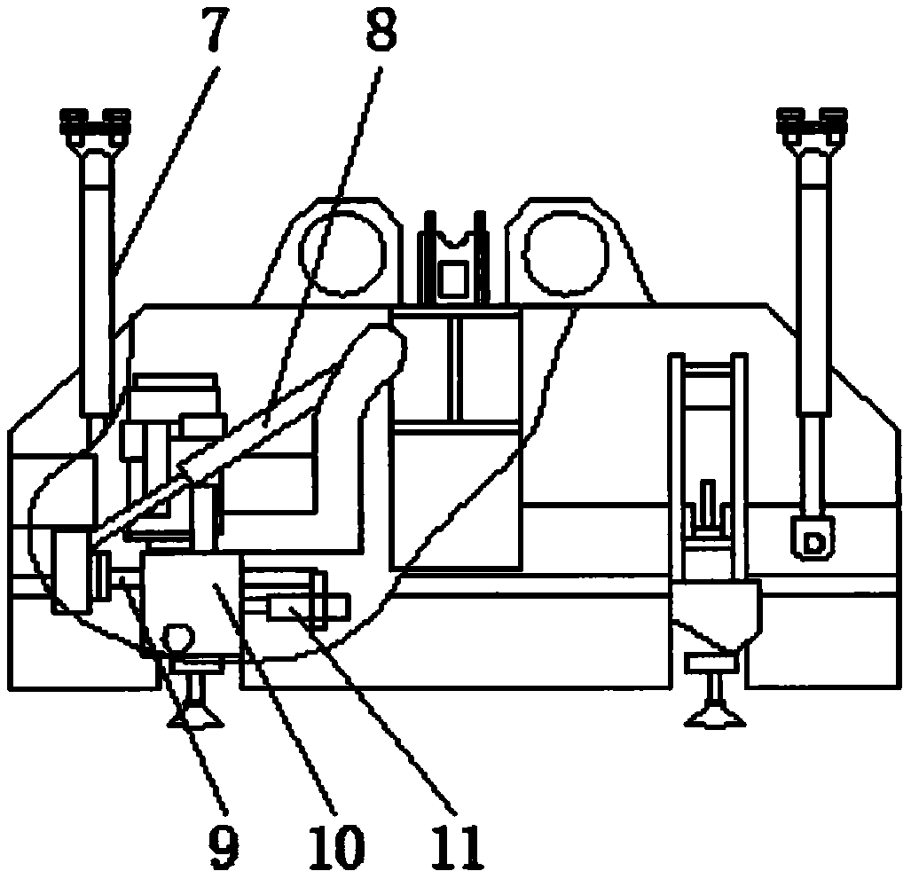
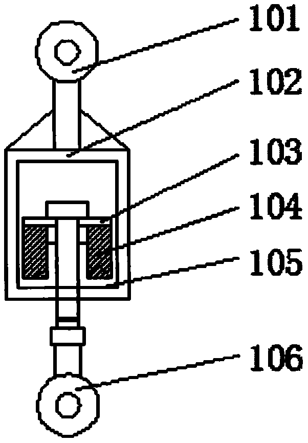
[0019] see Figure 1-3 , the present invention provides a technical solution: a rail grinding trolley, including a draw bar 1, a car body tie rod 101, a draw frame 102, a support plate 103, a rubber stack 104, a pull plate 105, a trolley tie rod 106, a vehicle frame 2, and a walking Wheel 3, grinding unit 4, grinding motor 401, grinding stone 402, electric push rod 403, dust collection channel 5, derailment protection device 6, lifting device 7, deflection ele...


PUM


Abstract

The invention discloses a rail grinding trolley. The rail grinding trolley comprises a frame, a grinding unit and derailment protection devices, wherein traction rods are separately arranged on the upper two sides of the frame, walking wheels are fixed to the lower part of the frame, the grinding unit is arranged in the frame, a dust collection channel is arranged on the upper part of the frame, the derailment protection devices are fixed to the left side and right side of the frame, lifting devices are arranged on the two sides of the inner part of the frame, deflection electric cylinders arearranged below the lifting devices, guide rods are arranged on the lower parts of the deflection electric cylinders, guide seats are arranged on the outer sides of the guide rods, and electric cylinders are fixed to one side of the guide seats. The rail grinding trolley is provided with a transverse moving structure capable of moving horizontally conveniently, and the guide seats can move on theguide rods under the driving action of the electric cylinders, so that the transverse moving of the grinding unit is realized, obstacles on both sides of a rail are conveniently avoided during grinding, and the operation range is expanded.

Description

technical field [0001] The invention relates to the technical field of rail grinding, in particular to a rail grinding trolley. Background technique [0002] The rail is a kind of track for driving, and the running surface is required to be smooth, so it needs to use a grinding device to polish its surface. Generally, the traction structure used by the rail grinding trolley adopts a steel drawbar at one end and an elastic drawbar at the other end. The traction force is always transmitted through the steel tow bar. When grinding, it is in the traction state when driving in the forward direction, and in the push state when driving in the reverse direction. [0003] The traction structure of the existing grinding vehicle is easy to run in the reverse direction, which not only affects the grinding quality, but also easily causes the small curve of the vehicle to derail, and when the grinding unit controls the angle deflection through the oil cylinder, the oil cylinder is easy to...

Claims


Application Information

Patent Timeline
Patent Type & Authority Applications(China)
IPC IPC(8): E01B31/17
Inventor 邹洪波
Owner 长沙瀚鹏电子技术有限公司
Learn More