
Suspension type single track vehicle traction suspension device applied to large ramp and method

A vehicle traction and suspension device technology, which is applied in the direction of the lateral relative movement device between the underframe and the bogie to achieve the effects of improving load distribution, simple structure and reasonable design

Pending Publication Date: 2019-05-14
CHINA RAILWAY BAOJI BRIDGE GRP
View PDF0 Cites 0 Cited by
  • Summary
  • Abstract
  • Description
  • Claims
  • Application Information

AI Technical Summary

Problems solved by technology

A rack-and-pinion drive reducer is arranged in the middle of the bogie, and the traction suspension device is connected to the beams on both sides of the bogie frame through a U-shaped beam to solve the problem of center pin installation

Method used


Image

  • Suspension type single track vehicle traction suspension device applied to large ramp and method
  • Suspension type single track vehicle traction suspension device applied to large ramp and method
  • Suspension type single track vehicle traction suspension device applied to large ramp and method

Examples


Embodiment 1

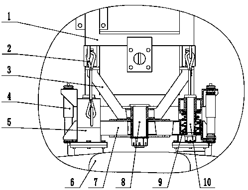
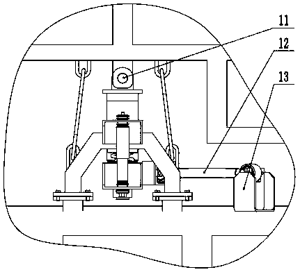
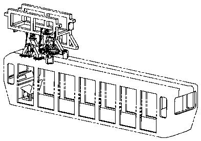
[0012] Embodiment 1: with reference to attached Figure 1-3 . A suspension type monorail vehicle traction suspension device suitable for large ramps, characterized in that: the U-shaped beam 3 is connected with the crossbeams on both sides of the bogie frame 1 using pin shafts 11, and the bottom of the U-shaped beam 3 is provided with pin holes. The middle vertical shaft 8 connects the U-shaped beam 3 with the bolster 7, two sets of shock absorbers 4 and shock absorbing springs 9 are symmetrically arranged on both sides of the bolster 7, the lower end of the shock absorber 4 is installed with the bolster 7, and the shock absorber 4 The upper end is installed with the suspension beam 5, and the damping spring 9 is installed in the bolster 7 and the suspension beam 5 respectively by the shock-absorbing connecting shaft 10, and the suspension beam 5 is installed with the mounting seat corresponding to the car body 6. The bolster 7 is provided with a drawbar mounting seat, the dr...

Embodiment 2

[0019] Embodiment 2: On the basis of Embodiment 1, a kind of working method of suspension type monorail vehicle traction suspension device, U-shaped beam 3 and bogie frame 1 both sides beams are connected by pin shaft 11, U-shaped beam 3 can be wound around Bearing pin 11 rotates back and forth, and the load transmitted to bogie frame 1 by pin 11 under any slope has only power like this, does not have front and rear bending moment. Improved load distribution to bogie load wheels. The bolster 7 is connected with the U-shaped beam 3 using an intermediate vertical shaft 8, and the connecting hole between the intermediate vertical shaft 8 and the bolster 7 and the U-shaped beam 3 adopts clearance fit, and the lower end of the intermediate vertical shaft 8 is fixed with a lock nut. In this way, the bolster 7 and the U-shaped beam 3 can rotate around the middle vertical shaft 8, and the middle vertical shaft 8 transmits axial load, left and right and front and rear bending moments. ...


PUM


Abstract

The invention relates to a suspension type single track vehicle traction suspension device applied to a large ramp and method. The suspension type single track vehicle traction suspension device applied to large ramp and method can solve the problem that a bearing wheel load distribution deviation is large under a large slope due to the fact that a vehicle body perpendicular load acts on a centerpin, and further can ensure the vehicle safety when a steering frame and a vehicle body connecting mechanism are damaged or invalid. A U-shaped beam is connected with cross beams on the two sides of the steering frame by using pin shafts, pin holes are formed in the bottom of the U-shaped beam, the U-shaped beam is connected with a swing bolster by using a middle vertical shaft, two groups of dampers and damping springs are symmetrically arranged on the two sides of the swing bolster, the swing bolster is mounted at the lower ends of the dampers, a suspension beam is mounted at the upper endsof the dampers, the damping springs are separately mounted on the swing bolster and the suspension beam through damping connecting shafts, and the suspension beam is mounted on a mounting seat corresponding to the vehicle body.

Description

technical field [0001] The invention relates to a method that can not only solve the problem that the vertical load of the vehicle body acts on the center pin, resulting in a large load distribution deviation of the load-bearing wheels under a large slope, but also ensure the safety of the vehicle when the connection mechanism between the bogie and the vehicle body is damaged or fails. The invention discloses a suspension type monorail vehicle traction suspension device and method suitable for large ramps, which belong to the field of monorail vehicle traction suspension manufacturing. Background technique [0002] The traction suspension device of the suspended monorail vehicle is an important mechanism connecting the bogie and the car body. It has the functions of transmitting traction force, braking force, carrying the weight of the car body, buffering the vibration and shock absorption of the vehicle during operation, and improving the ride comfort of the vehicle. sex. ...

Claims


Application Information

Patent Timeline
Patent Type & Authority Applications(China)
IPC IPC(8): B61F5/02
Inventor 张永亮张宁张冲马浩
Owner CHINA RAILWAY BAOJI BRIDGE GRP
Learn More