Air cooling wind tunnel wall manufacturing equipment of kilowatt-grade generators

An air-cooled air duct wall and manufacturing equipment technology, which is applied in the direction of manufacturing tools, metal processing equipment, grinding/polishing equipment, etc., can solve the problem of affecting the working state and power generation efficiency of generators, failing to meet production needs, troublesome cleaning of welding slag, etc. problems, to achieve the effect of improving cutting and polishing effects, improving convenience, and uniform movement speed

Active Publication Date: 2019-05-14
上海福源智业投资集团有限公司
View PDF11 Cites 0 Cited by
  • Summary
  • Abstract
  • Description
  • Claims
  • Application Information

AI Technical Summary

Problems solved by technology

[0002] Electricity is one of the important energy sources in today's society. If a city has insufficient electricity, it will affect the overall development of the city. Therefore, every city will have a large number of large-scale power generation equipment, at least kilowatt-level generators. In the process of power generation, huge heat will be generated. If the heat is not dissipated, it will seriously affect the working status and power generation efficiency of the generator, and even cause the generator to fail.
[0003] At present, the air-cooled duct pipe is used to conduct the heat of the generator, but the duct pipe has to go through many processes in the production process. After the duct pipe is welded, there will be more welding slag on the inner wall and the outer wall, and the outer wall will have more welding slag. The welding slag is easy to clean, but the cleaning of the welding slag on the inner wall is more troublesome. The existing device is not simple and convenient enough to deal with the welding slag on the inner wall, and cannot meet the production needs

Method used


Image

  • Air cooling wind tunnel wall manufacturing equipment of kilowatt-grade generators
  • Air cooling wind tunnel wall manufacturing equipment of kilowatt-grade generators
  • Air cooling wind tunnel wall manufacturing equipment of kilowatt-grade generators

Examples


Embodiment Construction

[0021] The following will clearly and completely describe the technical solutions in the embodiments of the present invention with reference to the accompanying drawings in the embodiments of the present invention. Obviously, the described embodiments are only some, not all, embodiments of the present invention.

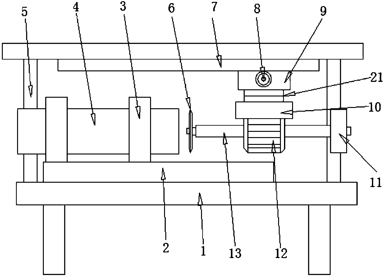
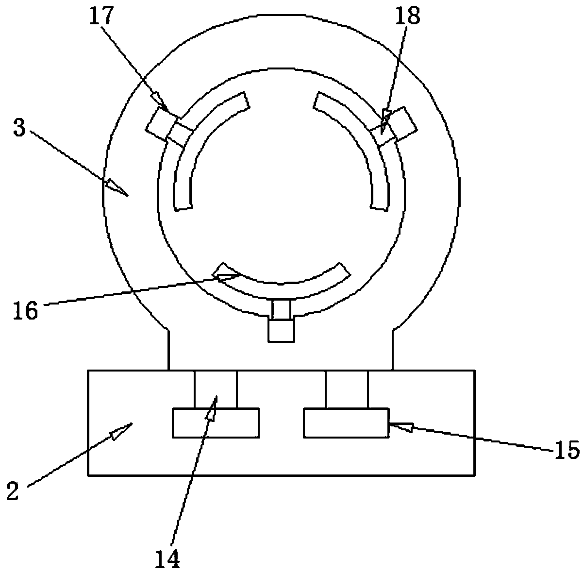
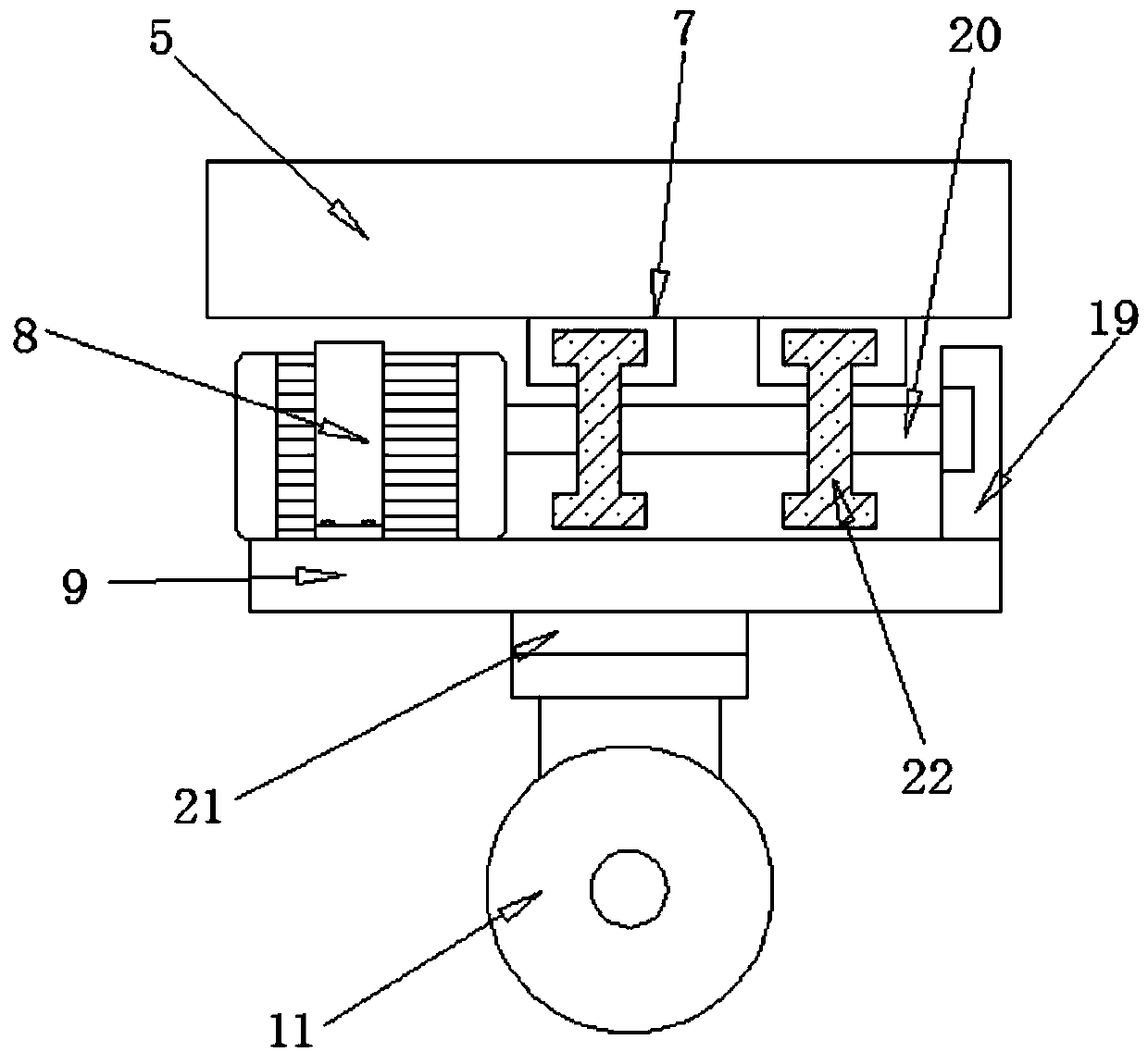
[0022] refer to Figure 1-3 , a kilowatt-level generator air-cooled air duct wall manufacturing equipment, including a processing frame 1, a rotating seat 21 and a fixed seat 3, the top outer wall of the processing frame 1 is fixed with a sliding frame 5 by bolts, and the bottom outer wall of the sliding frame 5 is fixed with two bolts. Equidistantly distributed guide rails 7, the outer wall of the bottom of the rotating seat 21 is fixed with a motor base 10 by bolts, and the outer wall of the bottom of the motor base 10 is fixed with a biaxial motor 12 by bolts, so that the device can be deslagging and polished without changing equipment, improving In order to impro...


PUM


Abstract

The invention discloses air cooling wind tunnel wall manufacturing equipment of kilowatt-grade generators. The air cooling wind tunnel wall manufacturing equipment comprises a processing frame, a rotating seat and a fixing seat, wherein a sliding frame is fixed to the outer wall of the top of the processing frame through bolts; two guide rails which are distributed in the equal distance are fixedto the outer wall of the bottom of the sliding frame through bolts; a motor seat is fixed to the outer wall of the bottom of the rotating seat through bolts; a dual-shaft motor is fixed to the outer wall of the bottom of the motor seat through bolts; and transmission shafts are respectively welded to one ends of two output shafts of the dual-shaft motor, and a cutter seat and a polishing wheel mounting seat are separately welded to one ends of the transmission shafts. According to the air cooling wind tunnel wall manufacturing equipment disclosed by the invention, the diameter of a cutter is the same as the inner diameter of a wind channel pipe, so that in the advancing process of the cutter, protruded welding slags are removed; after removal is completed, the dual-shaft motor is rotated,so that a polishing wheel enters the inner part of the wind channel pipe again for polishing, and the convenience of removing the welding slags of the manufacturing equipment is improved; and besides,the device can perform slag removing and polishing without replacing the equipment, so that the practicality of the device is improved.

Description

technical field [0001] The invention relates to the technical field of power generation equipment, in particular to the manufacturing equipment of air duct walls. Background technique [0002] Electricity is one of the important energy sources in today's society. If a city has insufficient electricity, it will affect the overall development of the city. Therefore, every city will have a large number of large-scale power generation equipment, at least kilowatt-level generators. In the process of power generation, huge heat will be generated. If the heat is not dissipated, it will seriously affect the working state and power generation efficiency of the generator, and even cause the generator to malfunction. [0003] At present, the air-cooled duct pipe is used to conduct the heat of the generator, but the duct pipe has to go through many processes in the production process. After the duct pipe is welded, there will be more welding slag on the inner wall and the outer wall, an...

Claims


Application Information

Patent Timeline
Patent Type & Authority Applications(China)
IPC IPC(8): B24B27/033B24B5/40
Inventor 袁小乔陈旭明
Owner 上海福源智业投资集团有限公司
Why Eureka
Try Eureka