VOCs (Volatile Organic Compounds) waste gas adsorbent regeneration pyrolysis furnace

A technology of adsorbent regeneration and pyrolysis furnace, which is applied in the direction of filter regeneration, combustible gas purification, combustible gas purification/transformation, etc. It can solve problems such as leakage, VOCs exhaust gas sealing failure, and no solution for electric heating purification filter elements. To achieve the effect of reducing pollutant emissions

Inactive Publication Date: 2019-05-14
唐钢美锦(唐山)煤化工有限公司
View PDF4 Cites 0 Cited by
  • Summary
  • Abstract
  • Description
  • Claims
  • Application Information

AI Technical Summary

Problems solved by technology

[0003] Existing technology-Aiming at the practical problems of large air volume VOCs waste gas treatment, the technical solution of the electrothermal purification filter element is proposed for the enclosure structure, the air inlet surface, and the air outlet surface with one or more layers of porous sieve plates or adsorption beds filled with sieves. However, there is no solution for how to replace the electrothermal purification filter element in normal production after the adsorption of VOCs exhaust gas is saturated; prior art 2 proposes the use of molecular sieve runners and honeycomb activated carbon runners for VOCs exhaust gas adsorption and desorption for the practical problems of VOCs exhaust gas treatment , Concentration, and combustion technical solutions, it is undoubtedly feasible to use a mechanical runner to solve the technical solution of replacing the adsorbent after the VOCs exhaust gas is saturated, but the sealing problem must be solved for moving equipment such as the runner, especially the rotary The problem of VOCs exhaust gas leakage due to seal failure under continuous production conditions during wheel replacement

Method used


Image

  • VOCs (Volatile Organic Compounds) waste gas adsorbent regeneration pyrolysis furnace
  • VOCs (Volatile Organic Compounds) waste gas adsorbent regeneration pyrolysis furnace
  • VOCs (Volatile Organic Compounds) waste gas adsorbent regeneration pyrolysis furnace

Examples


Embodiment Construction

[0033] The present invention will be further described below in conjunction with the accompanying drawings and specific embodiments.

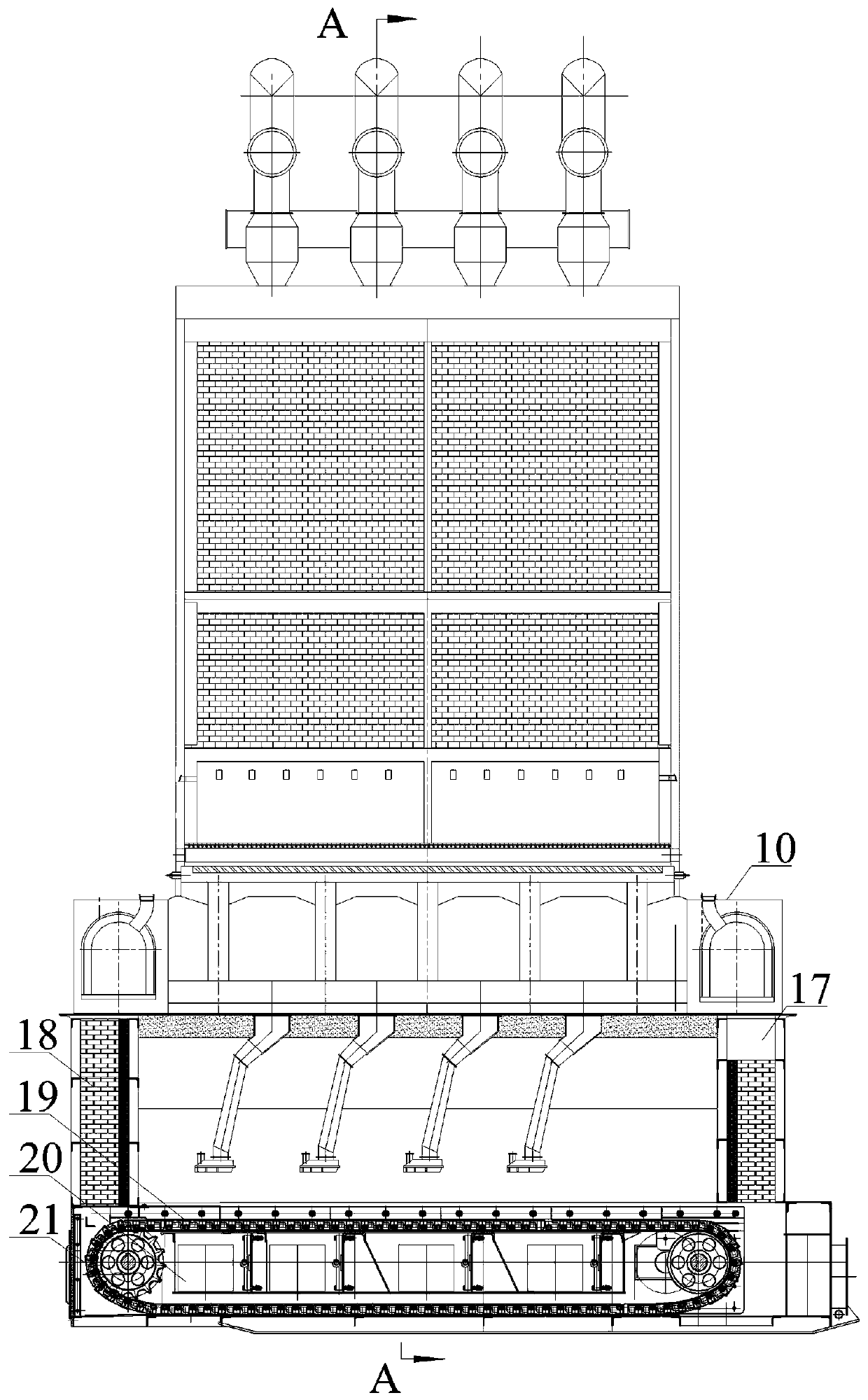
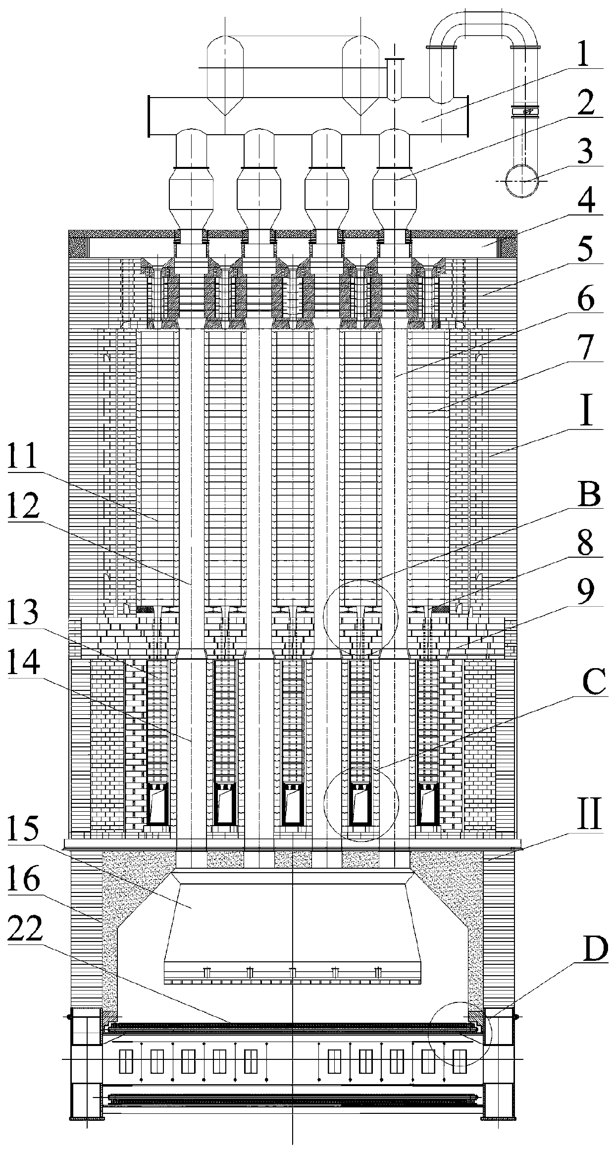
[0034] Such as figure 1 , figure 2 , image 3 , Figure 4 , Figure 5 As shown, a VOCs exhaust gas adsorbent regeneration pyrolysis furnace is characterized in that it includes a desorption pyrolysis furnace I and a chain drive grate bed II.

[0035] The desorption pyrolysis furnace I includes a desorption pyrolysis furnace body 5 and a feeding system 1 .

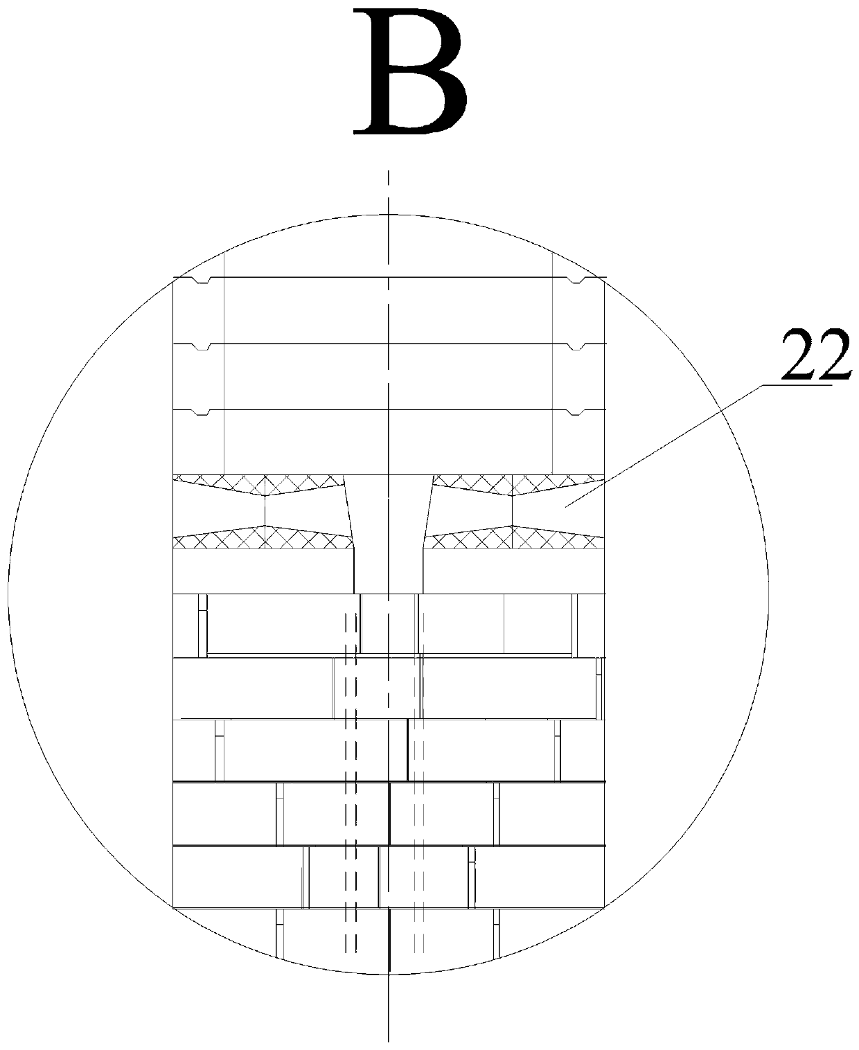
[0036] The desorption pyrolysis furnace body 5 is designed with a fire path 7 and a vertical path 6, the fire path 7 is for the circulation of high-temperature flue gas, the vertical path 6 is for the adsorbent to move and fall, and the fire path 7 and the vertical path 6 are adjacently built. The middle partition arch 9 divides the desorption pyrolysis furnace body 5 into upper and lower areas, that is, the upper area desorption pyrolysis area and the lower area heat storage area.

...


PUM


Abstract

The invention relates to the technical field of environment protection and in particular relates to a VOCs (Volatile Organic Compounds) waste gas adsorbent regeneration pyrolysis furnace which is characterized by comprising a desorption pyrolysis furnace and a chain driven grate bed, wherein the desorption pyrolysis furnace comprises a desorption pyrolysis furnace body and a supply system; a flamepath and a vertical channel are designed in the desorption pyrolysis furnace body; a high-temperature flue gas flows in the flame path; an adsorbent is moved and dropped down in the vertical channel;the flame path and the vertical channel are adjacently constructed; the supply system comprises a storage tank and an air injection collection tank; the air injection collection tank is used for introducing a tail gas discharged from the flame path to blow an adsorbent; the adsorbent is further mixed with a desorbed VOCs waste gas and conveyed into a pyrolysis chamber for oxidation and pyrolysisthrough grate bricks at the bottom of the desorption chamber; the chain driven grate bed comprises material legs and a chain driven grate bed body; a furnace tank and chain driven grate bed pieces aredesigned on the chain driven grate bed body; a smoke discharge hole is designed in the furnace tank; and the chain driven grate bed pieces comprise chain wheels, chains, grate bed pieces and air distribution plates.

Description

technical field [0001] The invention relates to the technical field of environmental protection, in particular to a regenerated pyrolysis furnace for VOCs waste gas adsorbents. Background technique [0002] Gaseous pollutants emitted by industry are the main source of atmospheric environmental pollutants, among which volatile organic compound waste gas (VOCs) is a gaseous pollutant that is seriously harmful to the environment, and it is also an occupational hazard that affects the health of operators in the workplace It is widely derived from chemical industries such as paints, coatings, coatings, lubricants, and rubber. Due to its huge destructive effect on the human body and the natural environment, the country has issued relevant laws and regulations to strictly control its governance and emissions. At present, the commonly used treatment methods of organic waste gas treatment technology include combustion method, chemical oxidation method, chemical absorption method, ad...

Claims


Application Information

Patent Timeline
Patent Type & Authority Applications(China)
IPC IPC(8): B01D53/02B01J20/34B01J20/20B01J20/18
Inventor 杨松
Owner 唐钢美锦(唐山)煤化工有限公司
Why Eureka
Try Eureka