Single rod type main bearing structure applicable to micro-nano remote sensing camera
A remote sensing camera and single-rod technology, applied in the field of space optical remote sensing, can solve the problems of high production cost, long processing cycle, and technological difficulty of integrated forming structures, achieve high specific stiffness, good mechanical and thermal stability, and reduce processing time. The effect of craft difficulty
- Summary
- Abstract
- Description
- Claims
- Application Information
AI Technical Summary
Problems solved by technology
Method used
Image
Examples
specific Embodiment approach 1
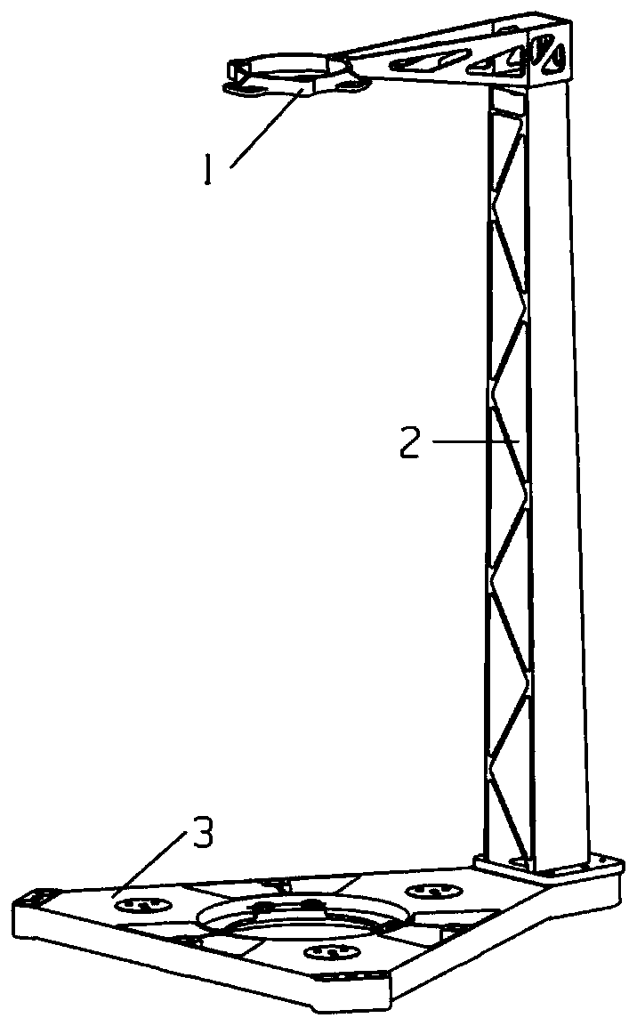
[0027] Specific implementation mode 1. Combination Figure 1 to Figure 8 Explain that this embodiment is suitable for the single-rod main load-bearing structure of the micro-nano remote sensing camera, which adopts a split-type single cantilever configuration, and consists of three parts: the secondary mirror bracket 1, the support rod 2 and the main back plate 3; according to figure 1 The assembly shown is implemented. The secondary mirror bracket 1 and the support rod 2, and the support rod 2 and the main backplane 3 are connected in the form of flanges, and epoxy resin glue is applied to the connection gap of each component to cure the connection.
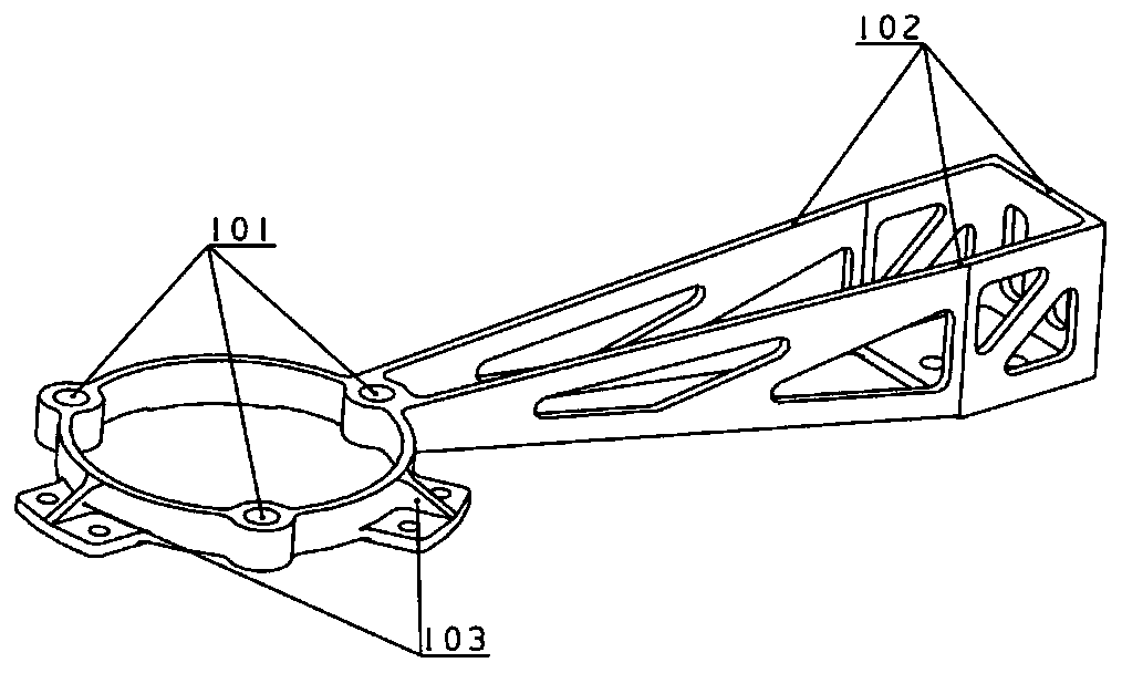
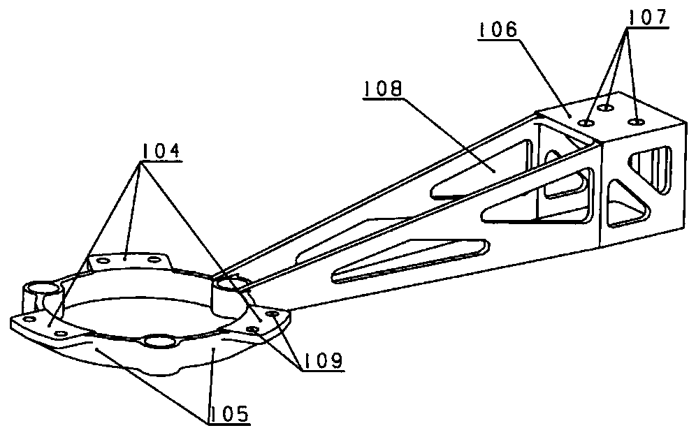
[0028]The secondary mirror support includes an outer frame 102 , inclined ribs 103 , a front panel 104 , an inner ring 105 , a lower panel 106 of the secondary mirror support and a cavity 108 . The front end of the outer frame 102 is connected to the inner ring 105, and the rear end is connected to the lower panel 106 of the se...
PUM
 Abstract
Description
Claims
Application Information
 - R&D
- Intellectual Property
- Life Sciences
- Materials
- Tech Scout
- Unparalleled Data Quality
- Higher Quality Content
- 60% Fewer Hallucinations
Browse by: Latest US Patents, China's latest patents, Technical Efficacy Thesaurus, Application Domain, Technology Topic, Popular Technical Reports.
© 2025 PatSnap. All rights reserved.Legal|Privacy policy|Modern Slavery Act Transparency Statement|Sitemap|About US| Contact US: help@patsnap.com


