
Automatic anti-uplift energy foundation pit support structure and construction method

A foundation pit enclosure and energy technology, which is applied in infrastructure engineering, excavation, refrigeration and liquefaction, etc., can solve the problems of slow construction period, long excavation time, and different effects, so as to eliminate the influence of assembly gaps and solve the problem. High footprint and cost, the effect of reducing exposure time

Pending Publication Date: 2019-05-10
ZHEJIANG UNIV CITY COLLEGE
View PDF0 Cites 3 Cited by
  • Summary
  • Abstract
  • Description
  • Claims
  • Application Information

AI Technical Summary

Problems solved by technology

Among them, although the segmented and layered excavation of the soil is effective in controlling the deformation of the soil, the excavation time becomes longer, which makes the planning and implementation of the construction organization more complicated; back pressure of the piled load requires concrete pouring at the bottom of the foundation pit It can only be carried out after solidification to a certain strength, and it cannot be reinforced and stabilized in time, which will increase the space-time effect at the bottom of the foundation pit and increase the risk of foundation pit uplift; setting up a partition wall and soil grouting reinforcement will control soil deformation. The effect is different, and will increase the project cost to a large extent; foundation pit precipitation is mainly used as an auxiliary means of controlling deformation and uplift, and its own control effect is limited; the construction process of the reverse method is more complicated, which will delay the construction period
At present, the excavation of the bottom of the foundation pit is usually sealed by direct pouring method, and the rapid back pressure of fabricated steel plates is rarely used, which has a slow onset time and cannot suppress the initial uplift deformation of the foundation pit.
On the other hand, the use of geothermal energy for energy conservation and environmental protection has been favored by the engineering community in recent years. It has gradually been combined with actual engineering structures to derive some new energy structures such as energy piles, energy tunnels, and energy retaining walls. The application of ground source heat pump technology in the protection structure is less, and the application prospect is great
[0004] To sum up, there are many existing control measures to prevent the deformation of large-scale deep foundation pit excavation in soft soil areas, but there are still some shortcomings such as unstable control effect, increased construction cost, delayed and extended construction period, and slow onset time.
At the same time, ground source heat pump technology has not been applied in the foundation pit enclosure structure. In order to play the supporting role and energy function of the enclosure structure, it is urgent to solve the problem by improving the technology.

Method used


Image

  • Automatic anti-uplift energy foundation pit support structure and construction method
  • Automatic anti-uplift energy foundation pit support structure and construction method
  • Automatic anti-uplift energy foundation pit support structure and construction method

Examples


Embodiment Construction

[0040] The present invention will be further described below in conjunction with the examples. The description of the following examples is provided only to aid the understanding of the present invention. It should be pointed out that for those skilled in the art, without departing from the principle of the present invention, some improvements and modifications can be made to the present invention, and these improvements and modifications also fall within the protection scope of the claims of the present invention.

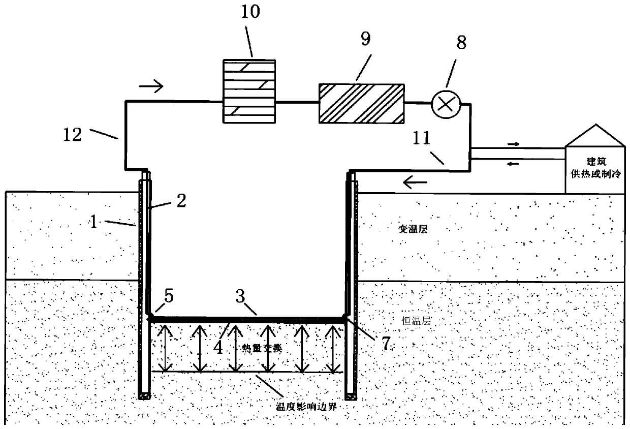
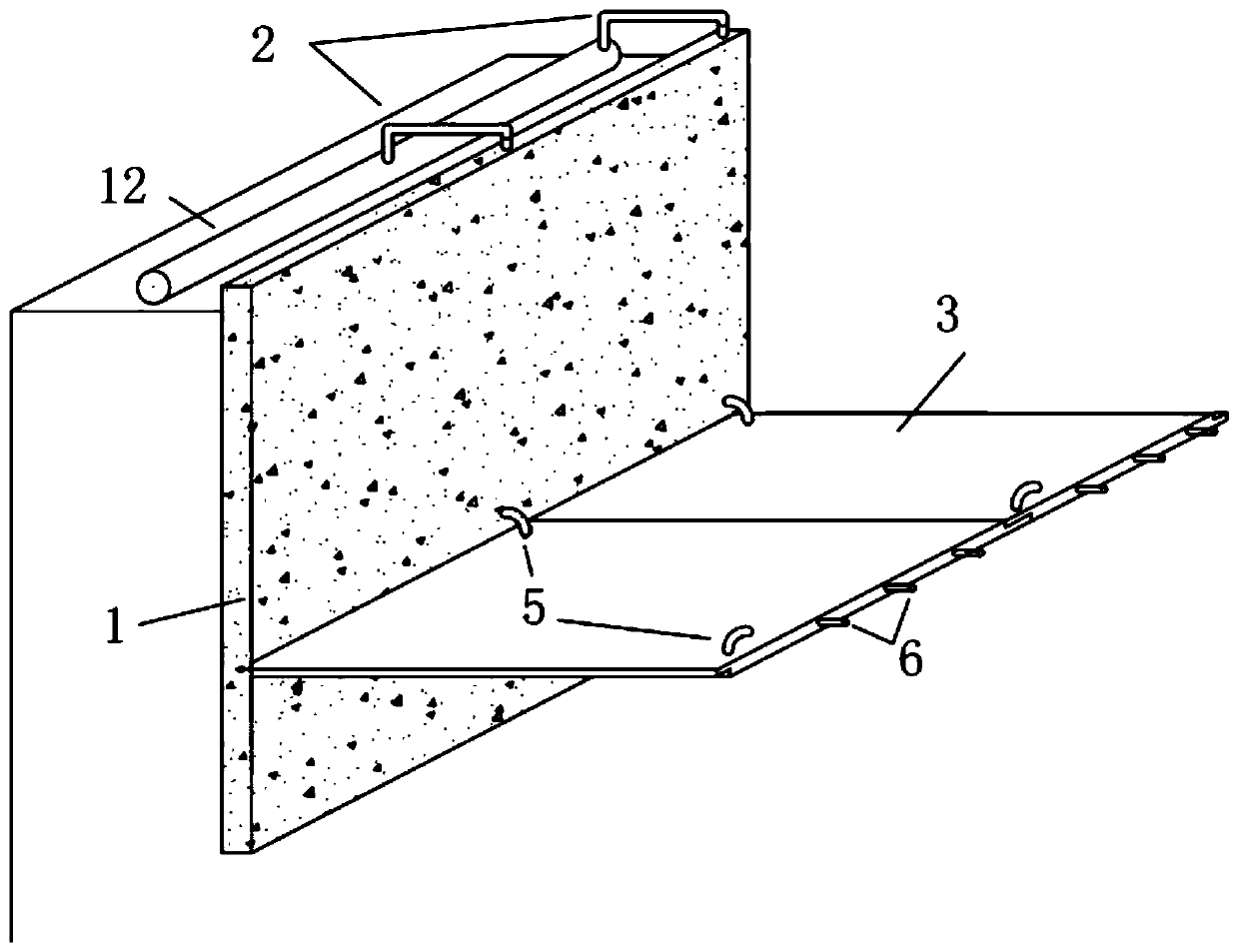
[0041] like figure 1 As shown, the foundation pit is supported by SMW piles as a whole, and the retaining wall of cement mixing piles is used for enclosure; I-beam is installed inside the retaining wall 1, and the inner side of the I-beam is the side of retaining wall 1 close to the foundation pit. 2. The bottom of the heat pipe 2 reaches the bottom of the foundation pit, and the top of the heat pipe 2 is a short distance above the top of the retaining wall 1, co...


PUM


Abstract

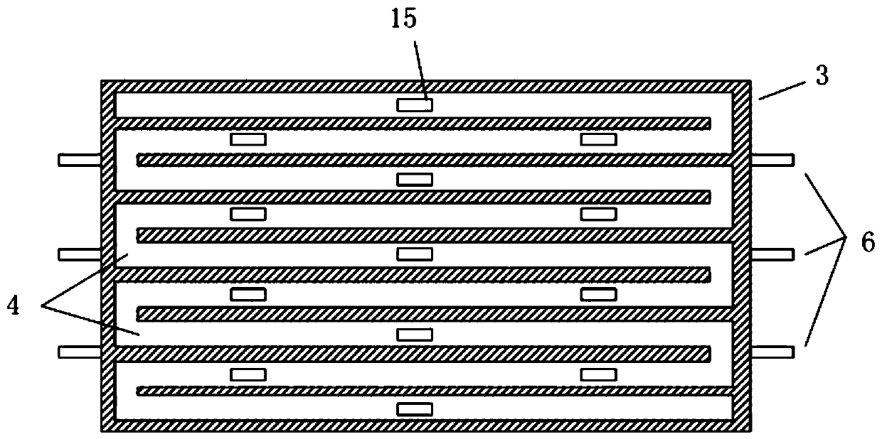
The invention relates to an automatic anti-uplift energy foundation pit enclosure structure which comprises a retaining wall, a heat conducting pipe, an assembled cover plate, a heat exchange pipeline, an arc-shaped connecting pipe, a pump machine, a ground source heat pump unit, a mud-water separator, a water tank, a water supply pipe and a water return pipe. A foundation pit is enclosed throughthe retaining wall, I-shaped steel is arranged in the retaining wall, the heat conducting pipe is arranged on the inner side of the I-shaped steel, and the bottom end of the heat conducting pipe reaches the bottom of the foundation pit. The top end of the heat conducting pipe is connected into the water supply pipe and the water return pipe and connected in series with the pump machine, the groundsource heat pump unit and the mud-water separator outside the foundation pit. The bottom of the foundation pit is covered with the assembled cover plate, and the two sides of the assembled cover plate are fixedly connected with notches of the retaining walls on the two sides through fixing end plugs. The structure has the beneficial effects that the assembled cover plate is convenient to construct and can realize quick back pressing. The slurry circulating system automatically discharges raised soil particles and releases soil pressure. Geothermal energy is circularly adopted by the foundation pit structure and used for peripheral heat supply or refrigeration. The assembly type design is efficient and flexible, and function conversion of the bottom cover plate is facilitated.

Description

technical field [0001] The invention belongs to the technical field of foundation pit support, and in particular relates to an automatic anti-uplift energy foundation pit enclosure structure and construction method, which is suitable for the prevention and treatment of large-area soil uplift deformation during foundation pit excavation, especially for soft soil It is especially suitable for the excavation of large-scale deep foundation pits in the region and the deformation control of the excavation of the upper foundation pits of existing tunnels. Background technique [0002] With the development of urbanization, it is inevitable to carry out various foundation pit excavation projects. The unloading effect produced by the excavation of the foundation pit will release the stress at the bottom of the foundation pit, resulting in uplift deformation, which threatens the safety of the foundation pit structure. For projects such as the excavation of the upper foundation pit of ...

Claims


Application Information

Patent Timeline
IPC IPC(8): E02D17/04E02D5/46E02D5/18F25B30/06
CPCY02E10/10
Inventor 魏纲齐永洁赵毅何骏飞戴子涵向青青胡慧静严助
Owner ZHEJIANG UNIV CITY COLLEGE
Learn More