A cooling device for explosive production

A cooling device and explosive technology, which is applied to explosives, explosives processing equipment, offensive equipment, etc., to achieve the effect of reducing equipment temperature, ensuring safety, and reducing temperature

Active Publication Date: 2021-08-06
JIANGXI GANZHOU GUOTAI SPECIALTY CHEM
View PDF3 Cites 0 Cited by
  • Summary
  • Abstract
  • Description
  • Claims
  • Application Information

AI Technical Summary

Problems solved by technology

[0003] The currently published Chinese patent authorization announcement number is CN208038344U, a high-temperature sensitized emulsion explosive body cooling device. Although simple heat exchange can be performed, a large amount of heat generated during the operation of the equipment is only processed through simple heat exchange. In this way, the predetermined demand that cannot be met still has potential safety hazards of explosion.

Method used


Image

  • A cooling device for explosive production
  • A cooling device for explosive production
  • A cooling device for explosive production

Examples


Embodiment 1

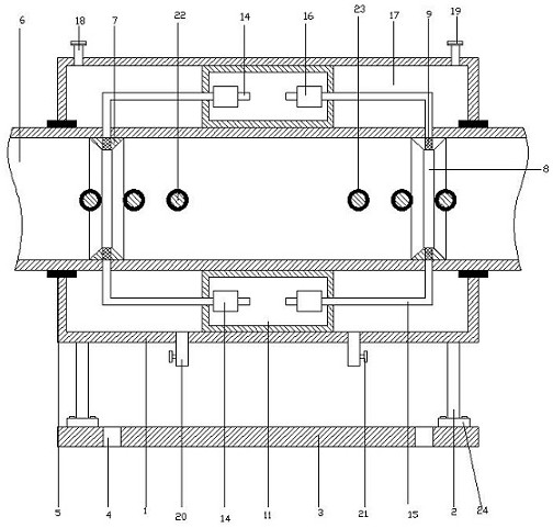
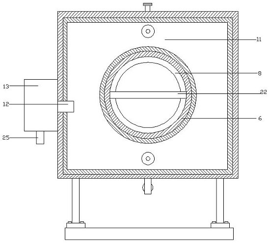
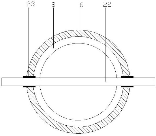
[0021] refer to Figure 1~3 , in an embodiment of the present invention, a cooling device for explosive production includes a connection cover 1, the left and right ends of the connection cover 1 are connected to the cooling pipe 6 through the first sealing ring 5, which can ensure that the cooling pipe 6 is sealed with the first The sealing of the ring 5, the middle part of the inner side of the connecting cover 1 is provided with a condensation chamber 11, the condensation chamber 11 is arranged on the outside of the cooling pipe 6, and a condenser 13 is installed on the connecting cover 1 at the rear side of the condensation chamber 11, which can condense the air , the lower side of the condenser 13 is provided with an air inlet pipe 25, and the condenser 13 is connected with the condensation chamber 11 through the cold air pipe 12, which can conveniently supply air to the condensation chamber 11, and the left and right ends of the inside of the cooling pipe 6 are respective...

Embodiment 2

[0024] The difference from the first embodiment is that the four corners of the lower side of the connecting cover 1 are fixedly welded with the supporting legs 2, the lower side of the supporting legs 2 is welded with the mounting block 24, and the lower side of the mounting block 24 is connected with the bottom plate 3 by bolts, which can facilitate the connection between equipment and The bottom plates 3 are installed with each other, and the four corners of the bottom plates 3 are provided with installation holes 4, which can facilitate the installation and fixing of the equipment.


PUM


Abstract

The invention relates to the field of explosive production, in particular to a cooling device for explosive production, which includes a connection cover, the left and right ends of the connection cover are connected to the cooling pipe through a first sealing ring, and the middle part of the inner side of the connection cover is provided with a condensation chamber for cooling. The first connecting convex ring and the second connecting convex ring are respectively installed at the left and right ends of the pipe, and the upper and lower ends of the first connecting convex ring and the second connecting convex ring are provided with dust-proof nets, and the dust-proof net at the left end passes through The first row of air ducts is connected to the condensation chamber, and the upper and lower sides of the dust-proof screen at the right end are connected to the condensation chamber through the second exhaust pipe. There are condensate storage chambers on the left and right sides of the condensation chamber, and inside the condensate storage chamber are The heat exchange tube, the connection between the heat exchange tube and the cooling pipe is connected through the second sealing ring. The present invention can effectively facilitate the condensation during the explosive production process, which can effectively ensure the safe production of the explosive and protect the working environment. personnel safety.

Description

technical field [0001] The invention relates to the field of explosive production, in particular to a cooling device for explosive production. Background technique [0002] Explosive material is a substance that can burn violently (that is, explode) in a very short period of time. It is a substance that explodes by its own energy under the action of a certain amount of external energy. Under normal circumstances, the chemical and physical properties of explosives are stable, but regardless of whether the environment is sealed or not, the amount of charge, or even in the case of zero oxygen supply from the outside world, as long as there is strong energy (provided by the detonator) to stimulate, the explosives will be released to the outside world. Carry out stable detonation type work. [0003] The currently published Chinese patent authorization announcement number is CN208038344U, a high-temperature sensitized emulsion explosive body cooling device. Although simple heat e...

Claims


Application Information

Patent Timeline
Patent Type & Authority Patents(China)
IPC IPC(8): C06B21/00
Inventor 冯亚东
Owner JIANGXI GANZHOU GUOTAI SPECIALTY CHEM
Why Eureka
Try Eureka