
An optimization method for robot welding path

A robot welding and welding path technology, applied in welding equipment, auxiliary welding equipment, welding/cutting auxiliary equipment, etc., can solve the problems of reducing robot welding efficiency, welding torch and cable life, etc., to improve welding efficiency and avoid large angles Effects of change and life extension

Active Publication Date: 2021-05-14
HANS LASER TECH IND GRP CO LTD +1
View PDF6 Cites 0 Cited by
  • Summary
  • Abstract
  • Description
  • Claims
  • Application Information

AI Technical Summary

Problems solved by technology

[0003] The present invention provides a method for optimizing the welding path of a robot, aiming to solve the problems in the prior art that the welding efficiency of the robot and the service life of the welding torch and the cable are reduced due to unreasonable planning of the welding path

Method used


Image

  • An optimization method for robot welding path
  • An optimization method for robot welding path
  • An optimization method for robot welding path

Examples


Embodiment Construction

[0046] In order to make the purpose, features, and advantages of the present invention more obvious and understandable, the technical solutions in the embodiments of the present invention will be clearly and completely described below in conjunction with the accompanying drawings in the embodiments of the present invention. Obviously, the described The embodiments are only some of the embodiments of the present invention, but not all of them. Based on the embodiments of the present invention, all other embodiments obtained by those skilled in the art without making creative efforts belong to the protection scope of the present invention.

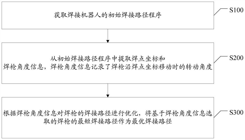
[0047] Such as figure 1 As shown, it is a flow chart of the method for optimizing the welding path of the robot provided by the first embodiment of the present invention.

[0048] The method comprises the steps of:

[0049] S100. Obtain an initial welding path program of the welding robot.

[0050] S200. Extract welding point coordinates ...


PUM


Abstract

The present invention is applicable to the field of welding robots, and provides a method for optimizing a welding path of a robot. The method includes: obtaining an initial welding path program of a welding robot, and extracting welding point coordinates and welding torch angle information from the initial welding path program. The welding torch angle The information records the rotation angle of the welding torch when it moves along the coordinates of the welding spot, optimizes the welding path of the welding torch according to the information of the welding torch angle, and takes the shortest welding path of the welding torch selected based on the information of the welding torch angle as the optimal welding path. According to the optimal welding path obtained by this method, the actual welding sequence of the robot can be re-planned, which can improve the welding efficiency of the welding robot, and at the same time avoid frequent large-angle changes in the posture of the welding torch and the cables connected to the welding torch during the welding process, extending the welding torch. and cable life.

Description

technical field [0001] The invention belongs to the field of welding robots, and in particular relates to an optimization method for a robot welding path. Background technique [0002] Robot welding has the advantages of high welding efficiency, stable welding quality, and low work intensity, and has been widely used in the field of industrial automation. But at present, robot automatic welding is not perfect in terms of welding path planning. Technicians often use experience to plan path, but this easily leads to unreasonable robot welding operation sequence, which reduces welding efficiency. Moreover, as the number of welding points increases, It is difficult to find the optimal welding path through experience alone, which increases the tact time of the entire welding process and prolongs the production cycle of the production line. In addition, for welding operations with complex working conditions, when the welding path planning is unreasonable, the posture of the weldi...

Claims


Application Information

Patent Timeline
Patent Type & Authority Patents(China)
IPC IPC(8): B23K37/02B25J9/16
Inventor 刘军豪范国成万虹陈根余陈焱高云峰
Owner HANS LASER TECH IND GRP CO LTD
Learn More