Automatic drilling tool and working method thereof

A drilling tool and drilling tool technology, which is applied in boring/drilling, drilling/drilling equipment, positioning devices, etc., can solve the problems of low efficiency of drilling tooling, complicated procedures, high equipment and environmental requirements, and achieve High drilling efficiency, accurate drilling positioning, and improved drilling efficiency

Inactive Publication Date: 2019-05-10
COSCO SHIPPING SHIPYARD (NANGTONG) CO LTD
View PDF2 Cites 1 Cited by
  • Summary
  • Abstract
  • Description
  • Claims
  • Application Information

AI Technical Summary

Problems solved by technology

[0003] In order to overcome the problems of low efficiency, complicated process, and high requirements on equipment and environment of drilling tooling existing in the prior art, the present invention provides an automatic drilling tooling and its working method, including trolley, automobile turning control system , electric motor, industrial computer, hydraulic motor, base, telescopic rod, optical power meter, drilling tool, reflector and fixture; the automobile turning control system, industrial computer, electric motor, hydraulic motor, base and telescopic rod are installed on On the trolley, the optical power meter and the drilling tool are installed on the base, the motor is connected to the industrial computer, the hydraulic motor and the optical power meter, and the drilling tool and the hydraulic motor are fixedly connected. The handle is fixed, and the side of the fixed handle is equipped with a reflector, the connection between the fixed handle and the telescopic rod is provided with an oil cup, and the top of the clamp is provided with a reflective patch

Method used


Image

  • Automatic drilling tool and working method thereof
  • Automatic drilling tool and working method thereof
  • Automatic drilling tool and working method thereof

Examples


Embodiment 1

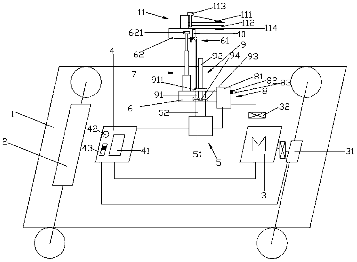
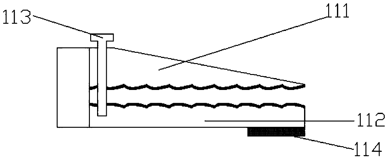
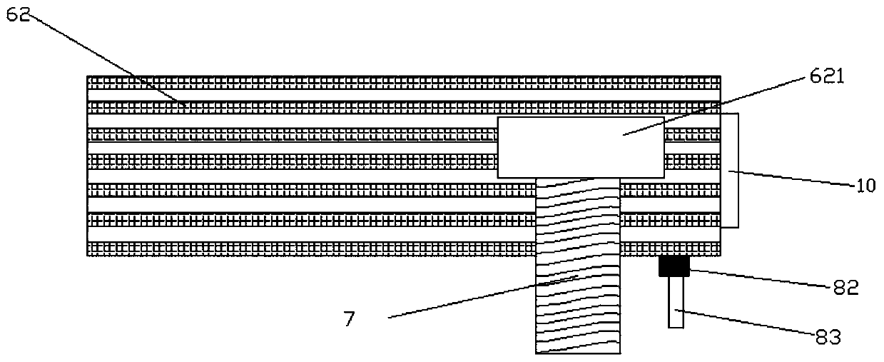
[0031] like figure 1 Shown: an automatic drilling tool and its working method, including a trolley 1, an automobile turning control system 2, an electric motor 3, an industrial computer 4, a hydraulic motor 5, a base 6, a telescopic rod 7, an optical power meter 8, a drilling tool 9. Reflector 10 and fixture 11; described automobile turning control system 2, industrial computer 4, electric motor 3, hydraulic motor 5, base 6 and telescopic rod 7 are all installed on the trolley 1, the optical power meter 8 and drill The tool 9 is installed on the base 6, the motor 3 is connected to the industrial computer 4, the hydraulic motor 5 and the optical power meter 8, and the drilling tool 9 and the hydraulic motor 5 are fixedly connected, and the telescopic rod 7 and the fixture 11 are provided with The handle 62 is fixed, and the mirror 10 is installed on the side of the fixed handle 62 , the connection part between the fixed handle 62 and the telescopic rod 7 is provided with an oil...

Embodiment 2

[0041] like figure 1 Shown: an automatic drilling tool and its working method, including a trolley 1, an automobile turning control system 2, an electric motor 3, an industrial computer 4, a hydraulic motor 5, a base 6, a telescopic rod 7, an optical power meter 8, a drilling tool 9. Reflector 10 and fixture 11; described automobile turning control system 2, industrial computer 4, electric motor 3, hydraulic motor 5, base 6 and telescopic rod 7 are all installed on the trolley 1, the optical power meter 8 and drill The tool 9 is installed on the base 6, the motor 3 is connected to the industrial computer 4, the hydraulic motor 5 and the optical power meter 8, and the drilling tool 9 and the hydraulic motor 5 are fixedly connected, and the telescopic rod 7 and the fixture 11 are provided with The handle 62 is fixed, and the mirror 10 is installed on the side of the fixed handle 62 , the connection part between the fixed handle 62 and the telescopic rod 7 is provided with an oil...


PUM


Abstract

The invention provides an automatic drilling tool and a working method thereof. The automatic drilling tool comprises a trolley, an automobile turning control system, a motor, an industrial personal computer, a hydraulic motor, a base, a telescopic rod, a light power meter, a drilling rig, a reflector and a clamp. The automatic turning control system, the industrial personal computer, the motor, the hydraulic motor, the base and the telescopic rod are all mounted on the trolley, the light power meter and the drilling rig are both mounted on the base, the motor is connected with the industrialpersonal computer, the hydraulic motor and the light power meter, the drilling rig is fixedly connected with the hydraulic motor, a fixed lifting handle is arranged between the telescopic rod and theclamp, the reflector is mounted on the side face of the fixed lifting handle, an oil cup is arranged on the joint of the fixed lifting handle and the telescopic rod, and a reflecting patch is arrangedon the top of the clamp. In the technical field of machining, a drilling tool in the prior art has the defects of being low in efficiency and complex in procedure, and the drilling tool with precisepunching, high efficiency and user friendliness is provided.

Description

technical field [0001] The invention relates to the technical field of mechanical processing, in particular to an automatic drilling tool and a working method thereof. Background technique [0002] There are many parts that need to be drilled in the machining process, and there are many problems in the drilling process of the hole; this article analyzes some problems in the drilling process; drilling usually refers to the Cylindrical inner surface. Holes are widely used in machining and manufacturing processes. For example, in our common threaded connections, threaded holes need to be drilled with a bottom hole before tapping. The drill bit that forms the threaded hole is bent during its own manufacturing process, and the bending of the drill bit will cause When the drill bit is drilling, the drill bit has a large radial runout, the size of the processed hole is larger than the required size, and the drilled hole may be skewed. For this problem, we can only replace a new qu...

Claims


Application Information

Patent Timeline
Patent Type & Authority Applications(China)
IPC IPC(8): B23B39/10B23Q3/06
Inventor 万家平仇明曹宇鹏沈冬健李荣王振刚钱保义施卫东姜佳星李接虎
Owner COSCO SHIPPING SHIPYARD (NANGTONG) CO LTD
Why Eureka
Try Eureka