Electric insulating oil sample bottle cleaning device
A cleaning device and insulating oil technology, which are applied in the directions of cleaning hollow objects, cleaning methods and utensils, and cleaning methods using liquids, etc., can solve the problems such as the ineffectiveness of waste liquid treatment, so as to ensure accuracy and reduce work intensity. , the effect of reducing environmental pollution
- Summary
- Abstract
- Description
- Claims
- Application Information
AI Technical Summary
Problems solved by technology
Method used
Image
Examples
Embodiment 1
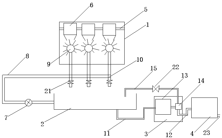
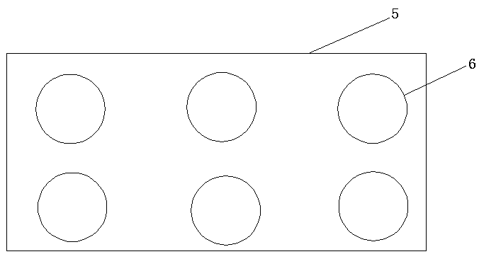
[0027] like figure 1 , figure 2 As shown, a cleaning device for sampling bottles of electric insulating oil includes a cleaning tank 1, a recovery tank 2, an oil-water separation device 3 and a waste liquid recovery device 4, the recovery tank 2 is located directly below the cleaning tank 1, and the cleaning tank 1 is provided with a box cover, and the inner wall of the cleaning box 1 is fixed with a fixing plate 5 and a cleaning device.
[0028] The fixing plate 5 is provided with several placement holes, and there are a plurality of insulating oil bottles 6 upside down in the placement holes, generally 6-8.
Embodiment 2
[0030] Embodiment 2 is different from Embodiment 1 in that the cleaning device includes a water pump 7, a cleaning pipe 8 and a shower head 9, one end of the cleaning pipe 7 is connected to the recovery tank 2, and the other end is passed through the water pump 7. It is connected with 3-4 spray heads 9, and several multi-way joints 10 are connected in series on the cleaning pipe between the water pump 7 and the spray heads 8. The multi-way joint 10 includes a four-way joint and a three-way joint, and the cleaning device cleans the insulating oil bottle with the cleaning liquid in the recovery pool 2 . The end of the multi-way joint 10 far away from the cleaning tank 1 is provided with a first solenoid valve 21, the other end of the first solenoid valve 21 communicates with the atmosphere, and the shape of the spray head is a divergent spherical shape, so The shower head 9 is provided with a plurality of holes.
[0031] The cleaning process is as follows: a certain volume of s...
Embodiment 3
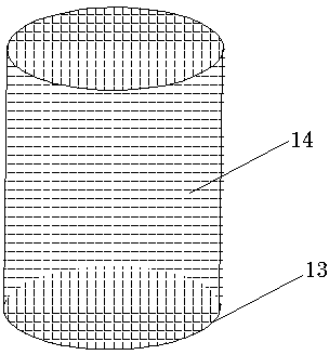
[0033] like image 3 , Figure 4 As shown, the difference between embodiment 3 and embodiment 2 is that the recovery tank 2 is connected with the oil-water separation device 3 through the first delivery pipeline 11, and the oil-water separation device 3 is connected with the waste water through the second delivery pipeline 12. Liquid recovery device 4 is connected. The oil-water separation device 3 includes a filter cartridge 13 and an oil-water separator, the filter cartridge 13 is connected to the first delivery pipeline 11, and the water outlet of the filter cartridge 13 is connected to the water inlet of the oil-water separator, so The water outlet of the oil-water separator is connected with the second delivery pipeline 12 . The filter cartridge 13 is cylindrical, and the outer surface of the filter cartridge 13 is provided with a filter 14 through which solid impurities in the oil-water mixture are filtered out, and the oil-water mixture enters the oil-water separator ...
PUM
 Abstract
Description
Claims
Application Information
 - R&D
- Intellectual Property
- Life Sciences
- Materials
- Tech Scout
- Unparalleled Data Quality
- Higher Quality Content
- 60% Fewer Hallucinations
Browse by: Latest US Patents, China's latest patents, Technical Efficacy Thesaurus, Application Domain, Technology Topic, Popular Technical Reports.
© 2025 PatSnap. All rights reserved.Legal|Privacy policy|Modern Slavery Act Transparency Statement|Sitemap|About US| Contact US: help@patsnap.com


