
Solid melting surface used for production of aluminum alloy parts

A technology for parts and aluminum alloys, which is applied in the field of solid melting furnaces for the production of aluminum alloy parts, can solve the problems of small load capacity, complicated opening and closing of the furnace door, and poor stability, so as to improve practicability, and the opening and closing process is convenient and fast. The effect of increasing efficiency

Pending Publication Date: 2019-05-03
DONGGUAN HONGXING MECHANICAL EQUIP
View PDF0 Cites 0 Cited by
  • Summary
  • Abstract
  • Description
  • Claims
  • Application Information

AI Technical Summary

Problems solved by technology

[0004] Aiming at the deficiencies of the prior art, the present invention provides a solid melting furnace for the production of aluminum alloy parts, which has the advantages of easy opening and closing of the furnace door, stable handling and good hot air circulation effect, and solves the problem of opening and closing the furnace door of the existing solid melting furnace. It is relatively cumbersome, which not only affects the efficiency of the solid melting of aluminum alloy parts, but also affects the practicability of the solid melting furnace, and when the existing solid melting furnace carries the workpiece, the carrier not only has a small load capacity, but also has poor stability when walking In addition, the hot air circulation effect of the existing solid melting furnace is poor, which affects the use of the solid melting furnace

Method used


Image

  • Solid melting surface used for production of aluminum alloy parts
  • Solid melting surface used for production of aluminum alloy parts
  • Solid melting surface used for production of aluminum alloy parts

Examples


Embodiment Construction

[0019] The following will clearly and completely describe the technical solutions in the embodiments of the present invention with reference to the accompanying drawings in the embodiments of the present invention. Obviously, the described embodiments are only some of the embodiments of the present invention, not all of them. Based on the embodiments of the present invention, all other embodiments obtained by persons of ordinary skill in the art without making creative efforts belong to the protection scope of the present invention.

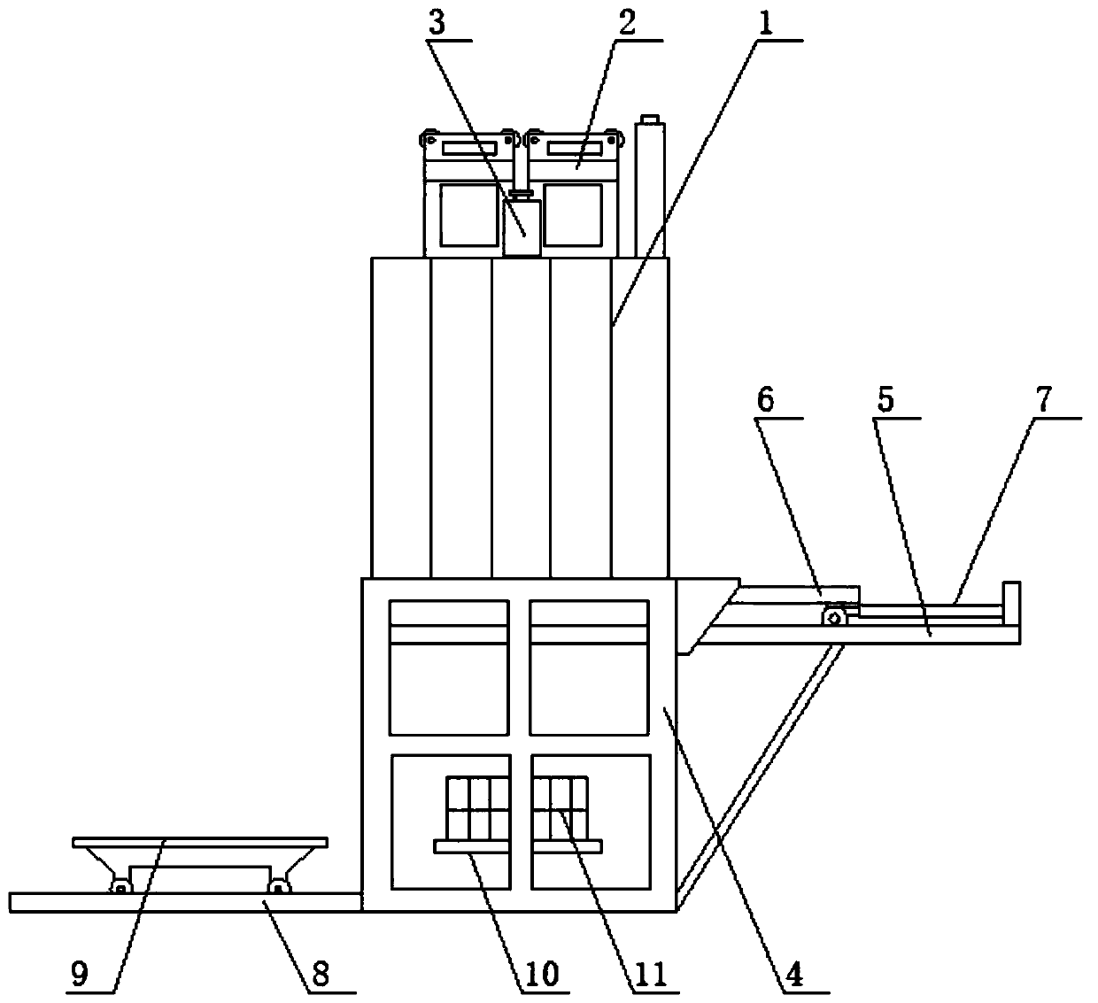
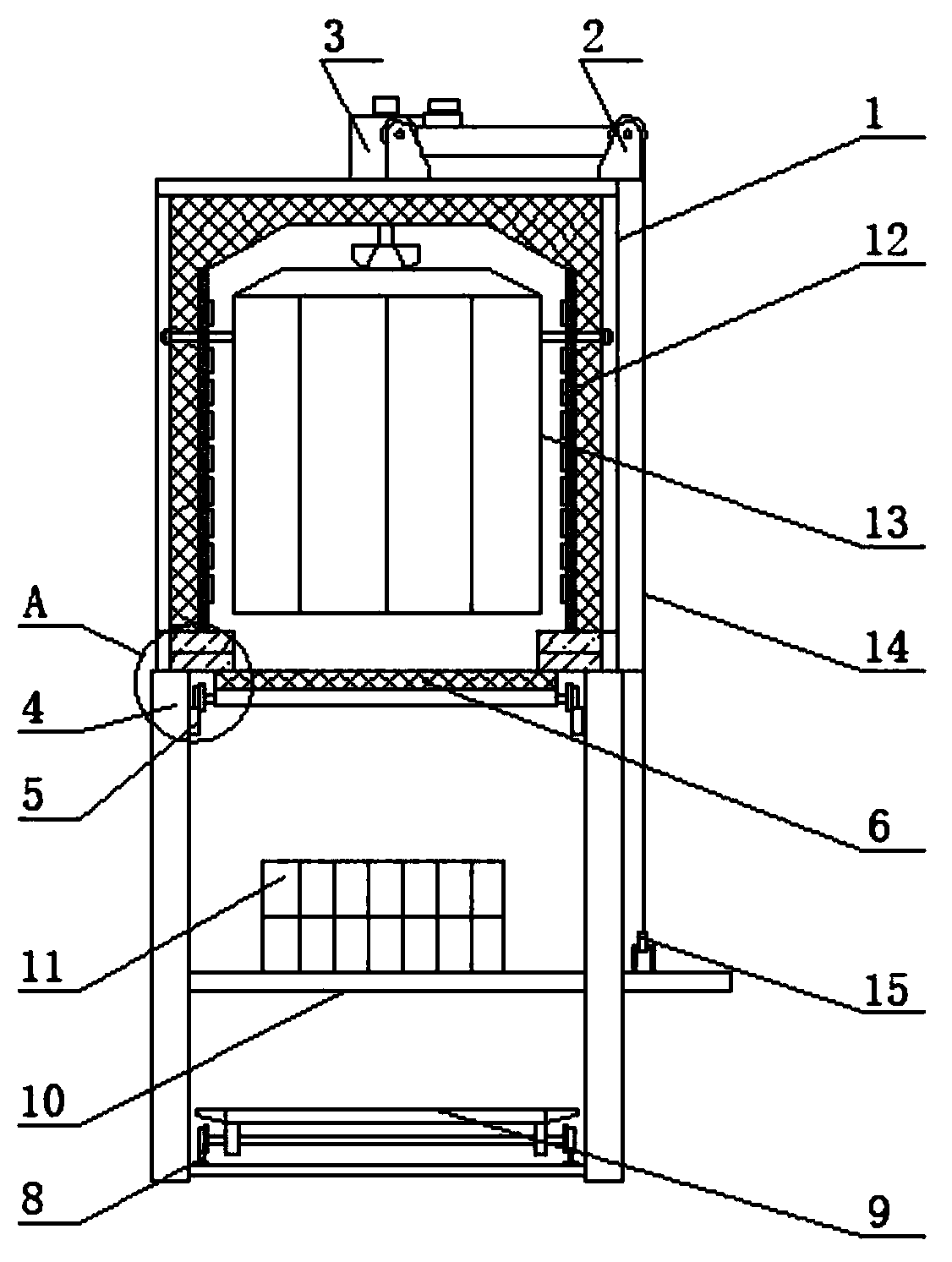
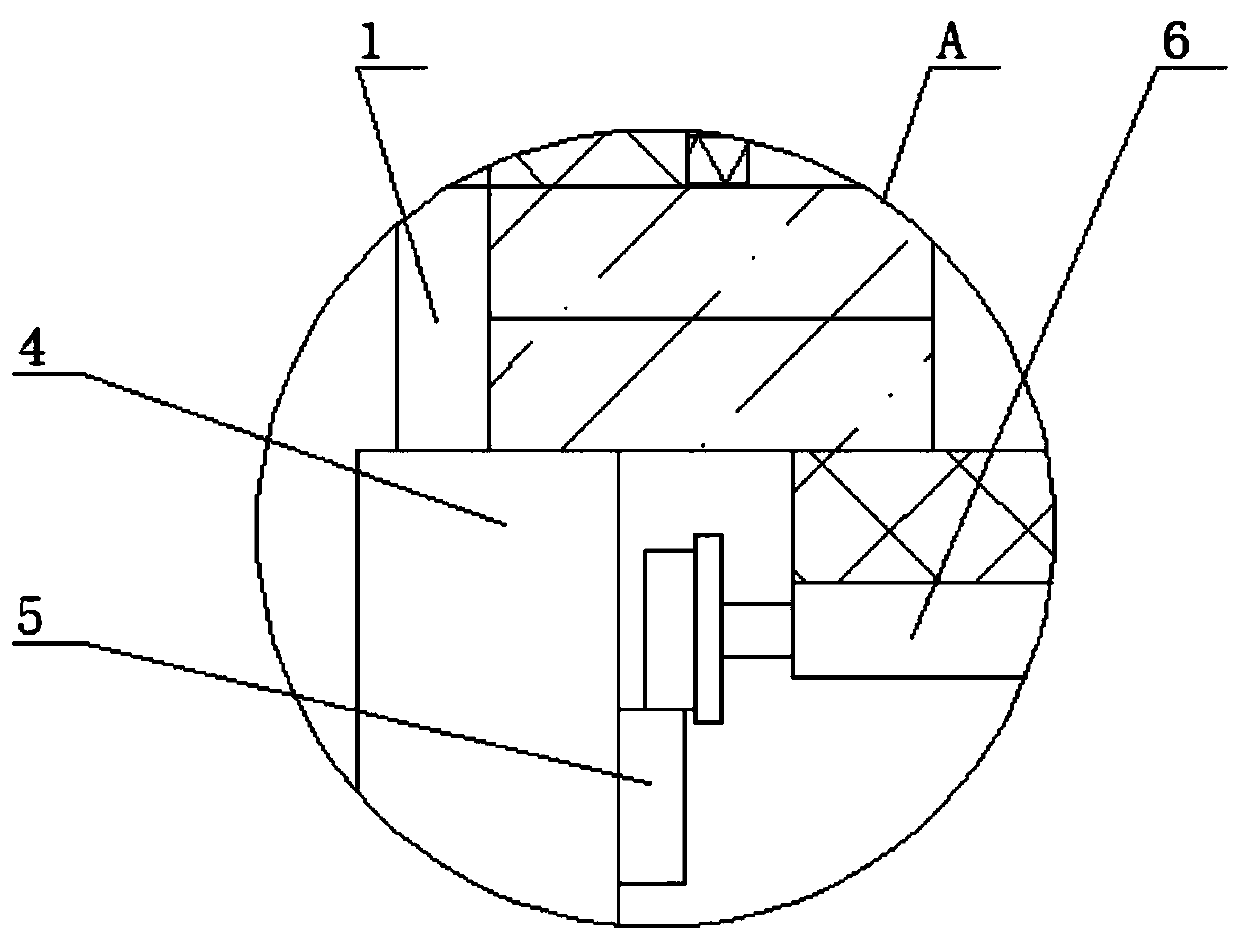
[0020] see Figure 1-3 , a solid melting furnace for the production of aluminum alloy parts, including a furnace body 1, the outer shell of the furnace body 1 is welded and formed by section steel, the inner wall of the furnace body 1 is made of heat-resistant steel plate, and the inner lining of the furnace body 1 is made of high-quality full fiber The structure can improve the thermal efficiency utilization rate and heat preservation of the sol...


PUM


Abstract

The invention relates to the technical field of solid melting furnaces, and discloses a solid melting furnace used for production of aluminum alloy parts. The solid melting furnace comprises a furnacebody. A lifting system is fixedly mounted at the top of the furnace body. A sesame steel wire rope is arranged on the right side of the lifting system. A hook is fixedly connected to the bottom end of the sesame steel wire rope. A hot-air circulation fan is fixedly mounted at the top of the furnace body. A bottom frame is fixedly mounted at the bottom of the furnace body. A sliding rail is arranged in the bottom frame. A furnace door is arranged at the top of the sliding rail. A cylinder is fixedly mounted on the right side face of the furnace door. A guide rail is fixedly mounted at the bottom of an inner cavity of the bottom frame. A workpiece transferring trolley located on the left side of the bottom frame is arranged at the top of the guide rail. According to the solid melting furnace used for production of the aluminum alloy parts, the cylinder is arranged, and the furnace door can be conveniently and rapidly opened and closed through the cylinder, so that the solid melting efficiency of the aluminum alloy parts is improved, and the practicability of the solid melting furnace is improved.

Description

technical field [0001] The invention relates to the technical field of solid melting furnaces, in particular to a solid melting furnace for producing aluminum alloy parts. Background technique [0002] Aluminum alloy is the most widely used non-ferrous metal structural material in industry, and has been widely used in aviation, aerospace, automobile, machinery manufacturing, shipbuilding and chemical industry. [0003] In the production process of aluminum alloy parts, it is necessary to use a solid melting furnace for solid melting treatment of its raw materials. The opening and closing of the furnace door of the existing solid melting furnace is relatively cumbersome, which not only affects the efficiency of solid melting of aluminum alloy parts, but also affects the practicality of the solid melting furnace. In addition, when the existing solid melting furnace carries workpieces, the carrier not only has a small load capacity, but also has poor stability when walking. In ...

Claims


Application Information

Patent Timeline
IPC IPC(8): C22F1/04
Inventor 莫政权肖世东
Owner DONGGUAN HONGXING MECHANICAL EQUIP
Learn More