
Coating layer-carried aero-engine part cleanness checking method and device thereof

An aero-engine and inspection method technology, applied in the direction of using liquid cleaning methods, cleaning methods and utensils, measuring devices, etc., to achieve good cleaning quality, prevent surface corrosion of parts, and high cleaning efficiency

Inactive Publication Date: 2019-05-03
SHENYANG LIMING INT POWER IND CO LTD
View PDF5 Cites 8 Cited by
  • Summary
  • Abstract
  • Description
  • Claims
  • Application Information

AI Technical Summary

Problems solved by technology

At present, there are few reports on the cleanliness inspection method of aero-engine coated parts. This paper provides a cleanliness inspection method for coated carbon steel parts. It not only has high cleaning efficiency and high cleaning quality, but also does not Damage to the base material and coating surface of the cleaned parts. At the same time, the process has the advantages of being stable and reliable, saving man-hours, and improving efficiency.

Method used


Image

  • Coating layer-carried aero-engine part cleanness checking method and device thereof
  • Coating layer-carried aero-engine part cleanness checking method and device thereof

Examples


Embodiment 1

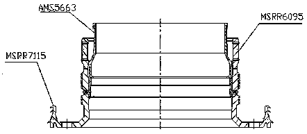
[0028] Embodiment 1: certain aero-engine parts with coating (see figure 1 (shown) is assembled from nickel-based high-temperature alloy, bearing steel, and stainless steel. Bearing steel material is easy to rust. Therefore, in order to avoid corrosion of parts and obtain good inspection results during cleaning and cleanliness inspection, an automatic cleaning machine is used for pre-cleaning. The cleaning solvent is petroleum. ether; from figure 1 It can be seen from the middle view that after the parts are assembled, there are many grooves, pores and teeth on the parts. The general simple soaking method is difficult to achieve the expected cleaning effect. In order to obtain a good cleaning effect, the method of pressure spraying petroleum ether is used. Cleaning, the specific steps are as follows:

[0029] (1) Use FRD-4000-PCS automatic cleaning machine to pre-clean, first use 3.72% (volume ratio) M-AERO-NS water-based cleaning solution to spray at 80°C for 4min; then heat...

Embodiment 2

[0036] Example 2: The difference between this example and Example 1 is that the content of the water-based cleaning solution of M-AERO-NS in step (1) in this example is 1.57% (volume ratio); Put the parts in an oven and dry for 90 minutes; the test result in step (6) is that the number of hard particles larger than 30 μm and smaller than 100 μm is 2;

Embodiment 3

[0037] Example 3: The difference between this example and Example 1 is that the content of the water-based cleaning solution of M-AERO-NS in step (1) in this example is 4.52% (volume ratio), and then the Spray with ion water for 1 minute; finally dry with clean hot air at 85°C for 3 minutes; in step (2), put the parts in an oven to dry for 120 minutes; in step (6), the test result shows that the hard particles are larger than 30 μm and less than 100 μm The number of is 0.


PUM

PropertyMeasurementUnit
boiling pointaaaaaaaaaa

Abstract

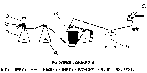
The invention relates to a coating layer-carried aero-engine part cleanness checking method. The method mainly comprises such contents as precleaning, drying, cleaning, cleaning solvent collection andcleanness checking; cleaning solvent uses petroleum ether; the petroleum ether is sprayed to clean parts by using a pressure cleaning gun; after three times of spray cleaning, all cleaning liquid iscollected for cleanness checking; a filter paper of 0.8 micron is adopted to filter the collected cleaning liquid; then, the particle size of hard impurity particles remained on the filter paper is checked; and when the number of hard particles of larger than 30 microns and smaller than 100 microns is not more than 5, related technical requirements are met. The method has the characteristics of high cleaning efficiency, high cleaning quality and convenience to operate, and meanwhile, cannot damage basal bodies of the cleaned parts.

Description

technical field [0001] The invention belongs to a part cleanliness inspection process, in particular to a method for inspecting the cleanliness of an aero-engine part with a coating. Background technique [0002] With the continuous improvement of the quality and reliability requirements of aviation products, cleanliness has become an important quality index of key components, which is directly related to the service life, efficiency and economic benefits of the engine. Therefore, it is particularly important to improve the cleanliness of products. Aeroengine manufacturing is a complex process from parts casting, processing, assembly, painting, and machine trial operation. After each process is completed, some mechanical impurities will remain. In order to ensure the reliability of the engine operation, the surface cleanliness of some key parts of the aero-engine is required to be relatively high. to the bearing surface, causing strain or excessive wear on the bearing surfa...

Claims


Application Information

Patent Timeline
Patent Type & Authority Applications(China)
IPC IPC(8): B08B3/02B08B13/00F26B21/00G01N21/00
Inventor 赵永岗吕红军丁志伟曾小莉李芳
Owner SHENYANG LIMING INT POWER IND CO LTD
Learn More