
Injection device for casting device and casting method

An injection device and injection port technology, which is applied in the field of injection devices, can solve the problems of reduced suction area, inappropriateness, increased sleeve manufacturing cost, etc., and achieve the effects of increasing the suction area, preventing advanced melt, and reducing replacement time.

Active Publication Date: 2021-12-10
UBE MASCH CORP LTD
View PDF22 Cites 0 Cited by
  • Summary
  • Abstract
  • Description
  • Claims
  • Application Information

AI Technical Summary

Problems solved by technology

[0008] (3) When the position of the suction port on the side of the sleeve is inappropriate for filling the melt
[0009] Furthermore, in the prior art of the above-mentioned Patent Document 1, there is only one suction port on the sleeve side, and if clogged with dross of the melt, the pressure cannot be sufficiently reduced, resulting in an increase in defects.
Since there is one suction port on the side of the sleeve, it is necessary to manufacture a sleeve with the suction port on the side of the sleeve at an optimal position according to the amount of melt supply, and the versatility is not good.
Therefore, it is necessary to hold various sleeves as consumables according to molds and products, and the production cost of sleeves increases.
Moreover, when the mold is replaced, it is necessary to replace it with a sleeve corresponding to the mold, and the adjustment time increases, which increases the cost
[0010] Furthermore, in the prior art of the above-mentioned Patent Document 1, even if clogging with dross of the melt occurs and the suction area is reduced or closed, it cannot be detected as an abnormality.
Casting continues without sufficient decompression, resulting in continuous production of defective products
In addition, dross of the melt enters the vacuum line, and malfunction of the solenoid valve that turns the vacuum on and off may occur.

Method used


Image

  • Injection device for casting device and casting method
  • Injection device for casting device and casting method
  • Injection device for casting device and casting method

Examples


Embodiment Construction

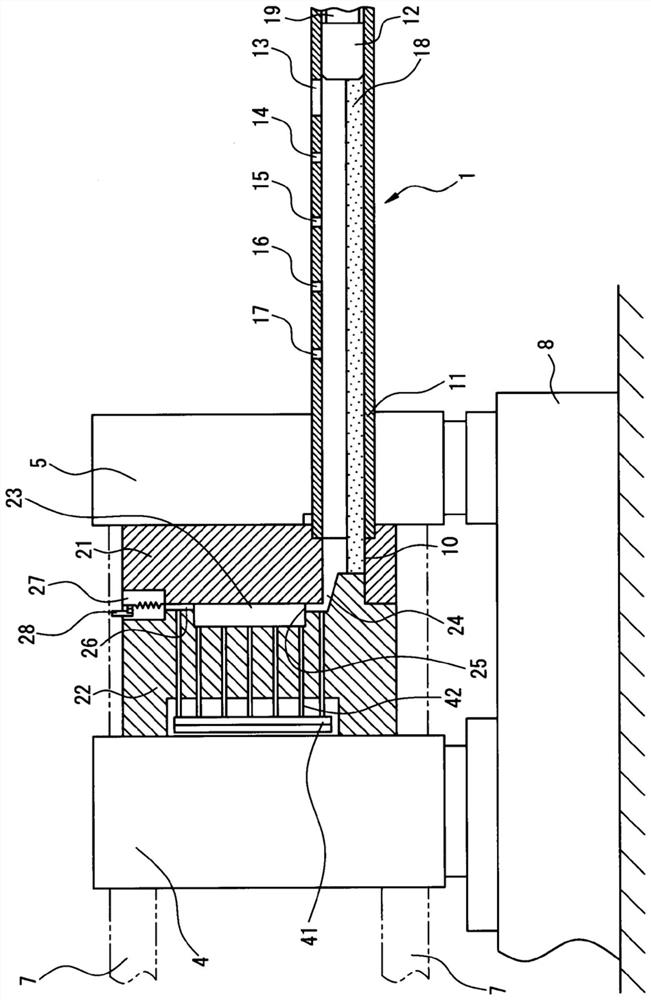
[0048] figure 1 It is a schematic side view (partial cross section is shown) of the die casting machine provided with the injection device 1 which concerns on one Embodiment of this invention.

[0049] In the die casting machine of this embodiment, the movable die 22 is provided on the movable platen 4 , and the fixed die 21 is provided on the fixed platen 5 . The movable platen 4 moves toward the fixed platen 5 side on the machine base 8 by means of a toggle mechanism, a ball screw mechanism, etc. for mold opening and closing, and a mold clamping mechanism (not shown). Thereby, the movable mold 22 and the fixed mold 21 are clamped (die clamped), and the cavity 23 is formed. Four connecting rods 7 pass through the movable platen 4 and the fixed platen 5 via through holes, and the movable platen 4 can freely move forward and backward relative to the fixed platen 5 along the connecting rods 7 . The fixed mold 21 and the movable mold 22 pass as figure 1 Engaged as shown, a c...


PUM


Abstract

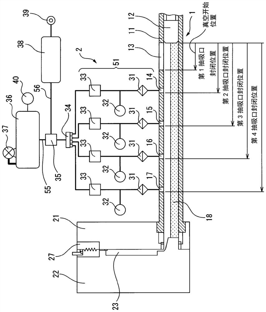
A casting device comprising an injection device and a vacuum device, the casting device being characterized in that the injection device comprises an injection plunger and a sleeve having a suction port connected to the vacuum device, the vacuum device comprising a vacuum capable of being selectively drawn using, without A suction port selection valve, a pressurized tank for blowing air to clean the suction path, and a vacuum tank for evacuating the inside of the sleeve, which includes a plurality of suction ports.

Description

technical field [0001] The present invention relates to an injection device for a casting device used in the manufacture of die-cast products, and a casting method using the injection device. Background technique [0002] In the case of producing castings made of light metal alloys, a die casting method, which is a method of pressurizing and filling a molten material (melt solution) into a mold, is often used. The die-casting method has high productivity because the melt in the injection sleeve (hereinafter, the injection sleeve is referred to as “sleeve”) is filled into the mold at high speed, and large and thin products can be manufactured. Moreover, it has the advantages of being able to produce products with high dimensional accuracy, fine casting structure and fine casting surface. On the other hand, since the melt is filled at a high speed, air is easily entrapped and blow holes (hole-shaped defects generated in castings) are easily generated. [0003] In recent year...

Claims


Application Information

Patent Timeline
Patent Type & Authority Patents(China)
IPC IPC(8): B22D17/14B22D17/20
CPCB22D17/14B22D17/20
Inventor 石桥直树釰祐一郎
Owner UBE MASCH CORP LTD
Learn More