
Wireless-sensor-oriented piezoelectric and electromagnetic combined type power supply device

A technology of wireless sensor and power supply device, applied in the field of micro-energy, can solve the problems of large current output, low response frequency, wide response frequency bandwidth, etc., and achieve the effects of wide energy collection frequency range, wide frequency response range, and high output voltage

Inactive Publication Date: 2019-04-26
JIANGSU UNIV
View PDF11 Cites 2 Cited by
  • Summary
  • Abstract
  • Description
  • Claims
  • Application Information

AI Technical Summary

Problems solved by technology

[0006] A piezoelectric power supply device is disclosed in the Chinese Patent Publication No. CN104283459B. The advantage of this device is that it can be used regardless of the size of the components, but this device cannot effectively reduce the natural frequency of the system, and the frequency response range of the system is relatively large. narrow
Chinese Patent Publication No. CN107359824A discloses a vehicle-mounted vibration piezoelectric power supply, which uses a suspension magnet and a limit magnet to ensure that the deformation of the piezoelectric vibrator does not exceed the allowable value. Compressive stress to avoid damage due to excessive tensile stress, but it is only suitable for large amplitude and high-intensity vibration environments, and the device does not use magnets to change the magnetic flux of the coil to supply power
[0007] Therefore, in order to overcome the problems existing in existing vibration energy harvesters, it is necessary to design a piezoelectric / electromagnetic composite power supply device with low response frequency, wide response frequency, large voltage output, and large current output.

Method used


Image

  • Wireless-sensor-oriented piezoelectric and electromagnetic combined type power supply device
  • Wireless-sensor-oriented piezoelectric and electromagnetic combined type power supply device

Examples


Embodiment Construction

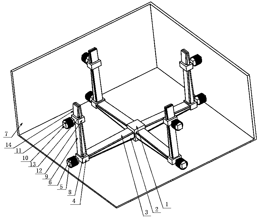
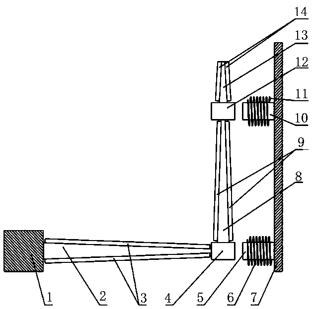
[0020] see figure 1 and figure 2 , the present invention includes a housing 7, a base 1 and four piezoelectric and electromagnetic composite power supply units. The outermost part is the casing 7, a base 1 and four piezoelectric and electromagnetic composite power supply units are located inside the casing 7, the base 1 is fixedly connected in the middle of the bottom plate of the casing 7, and the four piezoelectric and electromagnetic composite power supply units are connected Between the housing 7 and the base 1.

[0021] Each piezoelectric and electromagnetic composite power supply unit includes a first beam 2, a second beam 8, a third beam 13, a first permanent magnet 10, a second permanent magnet 5, a third permanent magnet 12, a fourth permanent magnet 4, The first coil 11 , the second coil 6 , the first piezoelectric sheet 3 , the second piezoelectric sheet 9 and the third piezoelectric sheet 14 . Wherein, the first beam 2 is arranged horizontally at the bottom of ...


PUM


Abstract

The invention discloses a wireless-sensor-oriented piezoelectric and electromagnetic combined type power supply device. A base is fixedly connected to the middle of the bottom of a shell, four piezoelectric and electromagnetic combined power supply units are connected between the shell and the base, and each combined power supply unit comprises a first beam, a second beam and a third beam, whereinthe inner ends of the four first beams are fixedly connected to four side faces of the base correspondingly; the outer end of each first beam is connected with a fourth permanent magnet, each fourthpermanent magnet is connected to the lower end of the corresponding second beam, the second beams are connected with third permanent magnets, and the third permanent magnets are connected to the lowerends of the third beams. First permanent magnets with opposite magnetic poles are arranged between the third permanent magnets and the shell, second permanent magnets with opposite magnetic poles arearranged between the fourth permanent magnets and the shell, coils are wound on the permanent magnets, and piezoelectric patches are bound to the lateral surfaces of every three beams. The base and the combined power supply units constitute an L-shaped beam and mass block structure which can be tuned to internal resonance, a piezoelectric power supply structure and an electromagnetic power supplystructure are combined, and large voltage and current can be output.

Description

technical field [0001] The invention belongs to the field of micro-energy technology, and specifically relates to a power supply device for wireless sensors, which is a composite power supply device that uses piezoelectric vibration energy and electromagnetic vibration energy to obtain potential. Background technique [0002] With the rapid development of microelectronics technology, micromachining technology and wireless sensing technology, electronic products such as embedded systems, radio frequency identification systems, wireless sensors and various implantable micro sensors have entered the stage of integration, miniaturization and In the era of low power consumption, traditional power transmission lines and chemical batteries can no longer meet the energy supply requirements of these tiny electronic devices. The vibration energy harvester based on MEMS technology uses the piezoelectric effect and electromagnetic induction phenomenon to convert the vibration mechanical...

Claims


Application Information

Patent Timeline
IPC IPC(8): H02N2/18H02K35/02
CPCH02K35/02H02N2/186
Inventor 何仁茆浪
Owner JIANGSU UNIV
Learn More