Testing device for testing shield cutter head-soil body intermediate lateral adhesion force

A technology of shield cutter head and test device, applied in the field of tunnel engineering, can solve the problems of lack of test equipment, unreasonable structure, lack of basis for value selection, etc.

Pending Publication Date: 2019-04-26
CHINA RAILWAY NO 5 ENG GRP +1
View PDF9 Cites 2 Cited by
  • Summary
  • Abstract
  • Description
  • Claims
  • Application Information

AI Technical Summary

Problems solved by technology

For example, the patent CN204436401U aims at the shortcomings of unreasonable structure and inconvenient maintenance of the cutter head torque input structure of the shield machine in the prior art, and provides a shield machine with a reasonable structure and easy assembly, replacement and maintenance in a narrow construction tunnel Machine cutter head torque input structure, the cutter head torque input structure includes motor, reducer, internal gear slewing support and torque input gear support structure; patent CN103899328A discloses a method for calculating the front torque of curved surface earth pressure balance shield cutter head, Provide reliable parameter control basis for shield construction; patent CN204784299U provides a simple structure, easy to operate and use, can realize the active disengagement function of the torque limiter, and can be easily reset after disengagement. protective device
To sum up, the cutter head is the core device of the shield machine, the soil load on the cutter head and its calculation method belong to the core technology of the shield machine, but the existing theory of cutter head torque calculation and the corresponding cutter head structure design It is mainly based on empirical formulas, especially the value of key parameters such as soil-cutterhead adhesion is lacking, and there is also a lack of relevant testing equipment

Method used


Image

  • Testing device for testing shield cutter head-soil body intermediate lateral adhesion force
  • Testing device for testing shield cutter head-soil body intermediate lateral adhesion force
  • Testing device for testing shield cutter head-soil body intermediate lateral adhesion force

Examples


Embodiment Construction

[0022] The present invention will be described in detail below in conjunction with the accompanying drawings and specific embodiments.

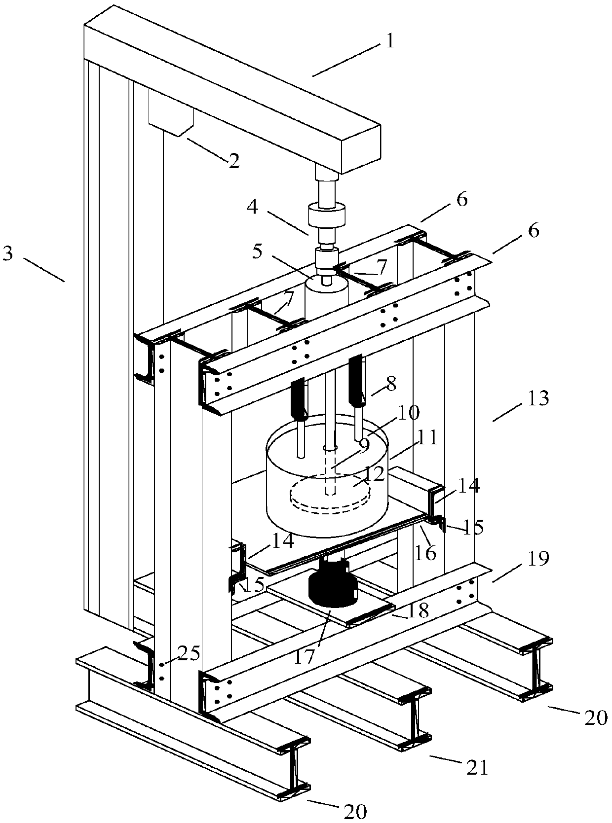
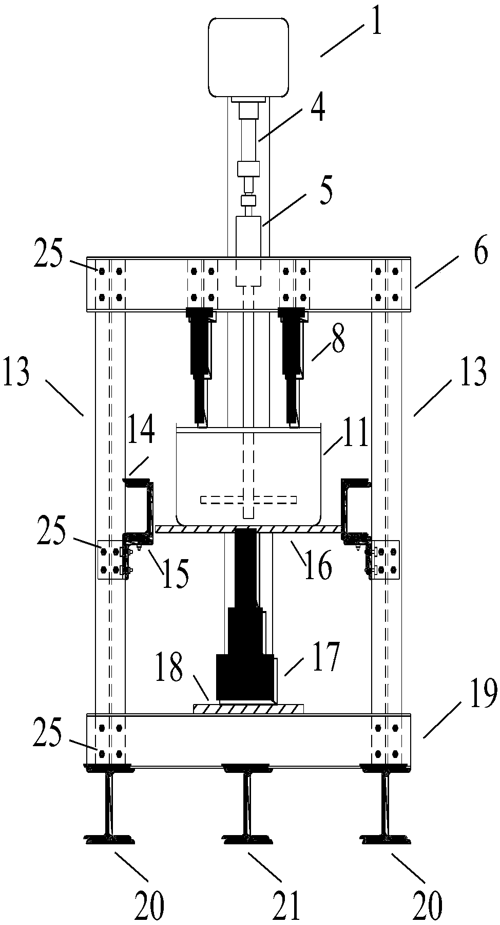
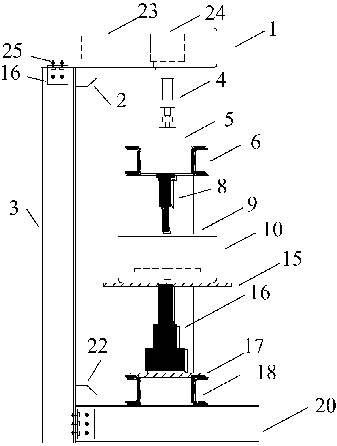
[0023] A test device for testing the dynamic lateral adhesion between shield cutterhead and soil, as attached figure 1 , 2 , Shown in 3, 4, the composition of this device is:

[0024] (1) Power rotation system: the rotating loading arm 1 and the base beam 21 are installed horizontally at both ends of the vertical load arm 3 respectively, and the rotating loading arm 1 and the base beam 21 are connected by angle steel 15, bolts 25 stiffening plate 2, stiffening plate The plate 22 is connected with the vertical bearing arm 3; a power mechanism 24, a reduction motor 23 and a shaft coupling 4 are installed on the rotating loading arm 1, and the shaft coupling 4 is connected with the vertical rotating shaft 9, and the rotating shaft 9 is driven by the rotating loading arm 1. The power mechanism 24 of the arm 1 is driven, and the rotation speed i...


PUM


Abstract

The invention discloses a testing device for testing shield cutter head-soil body intermediate lateral adhesion force. The device comprises a power rotary system, a lifting jack loading system and a soil box, wherein the power rotary system is composed of a rotary loading large arm (1), a vertical loading arm (3), a coupler (4), a torque sensor (5), a rotary shaft (9), a testing round disc (12), aforce transmission rod base beam (21) and the like; the lifting jack loading system comprises a loading lifting jack (8), a jacking lifting jack (17) and a jacking lifting jack bottom plate (18); thesoil box (11) is a container without cover, and a cover plate (10) which is used for loading the lifting jack is arranged on the container. The device has the advantages that the device can be used for simulating and testing of intermediate rotary dynamic adhesion resistance of the shield cutter head and a to-be-cut soil body, the soil body cutting difficulty of the cutter head can be evaluated through analyzed rotary dynamic lateral adhesion force and the observation of the wearing condition of a rotary round disc, and therefore reference is provided for the designing computation of the shield cutter head.

Description

technical field [0001] The invention relates to the field of tunnel engineering, in particular to a test device for testing the dynamic lateral adhesion between a shield cutter head and soil body. Sizing and cutterhead design reference service. Background technique [0002] With the acceleration of urbanization, traffic congestion is becoming a bottleneck problem restricting the further development of modern cities. In view of this, major countries in the world regard the development of urban rail transit as the growth point of a new round of urban economic development. In the process of urban rail transit construction, shield method construction has been widely used in the construction of rail transit projects represented by subway tunnels due to its advanced construction technology, safe construction technology and relatively small impact on the surrounding environment. . [0003] The excavation of the shield in the ground depends on the rotation of the cutter head to d...

Claims


Application Information

Patent Timeline
Patent Type & Authority Applications(China)
IPC IPC(8): G01N19/04G01M99/00
CPCG01M99/007G01N19/04
Inventor 李谷阳张细宝胡如成李晓亮龚振宇黄杉王海飞
Owner CHINA RAILWAY NO 5 ENG GRP
Why Eureka
Try Eureka