
High-strength brake hub for heavy truck

A heavy-duty, high-strength technology, used in brake types, drum brakes, brake actuators, etc., can solve the problems of small brake shoe action area, less than ideal braking effect, hydraulic oil leakage, etc. Fast response, low cost, uniform wear effect

Inactive Publication Date: 2019-04-26
河北百龙汽车配件股份有限公司
View PDF0 Cites 6 Cited by
  • Summary
  • Abstract
  • Description
  • Claims
  • Application Information

AI Technical Summary

Problems solved by technology

[0003] The technical problem to be solved by the present invention is to provide a high-strength brake hub for heavy-duty vehicles, which adopts the design of an electromagnetic rotary ring brake device, and pushes the push plate through an electromagnetic clutch when braking. Rotate, so as to push multiple brake pads to the brake drum at the same time, and realize the braking action under the action of multiple brake pads and brake drums. The bonding area of ​​the brake pads and the brake drum is larger, and the braking effect is better. It solves the problem that the brake shoe has a small active area and the braking effect is not ideal in the traditional drum brake; the torque of the push plate is controlled by controlling the current, so as to control the bonding strength of the brake pad and the brake drum, and finally realize the braking effect. The force is controllable, and only two wires are needed to realize the controlled transmission, eliminating the need for hydraulic pipes, hydraulic pumps and other original parts, and has the advantages of low cost, fast braking response, and no pollution. The cost of hydraulic pressure is high, and the problem of pollution caused by hydraulic oil leakage

Method used


Image

  • High-strength brake hub for heavy truck
  • High-strength brake hub for heavy truck
  • High-strength brake hub for heavy truck

Examples


specific Embodiment approach 1

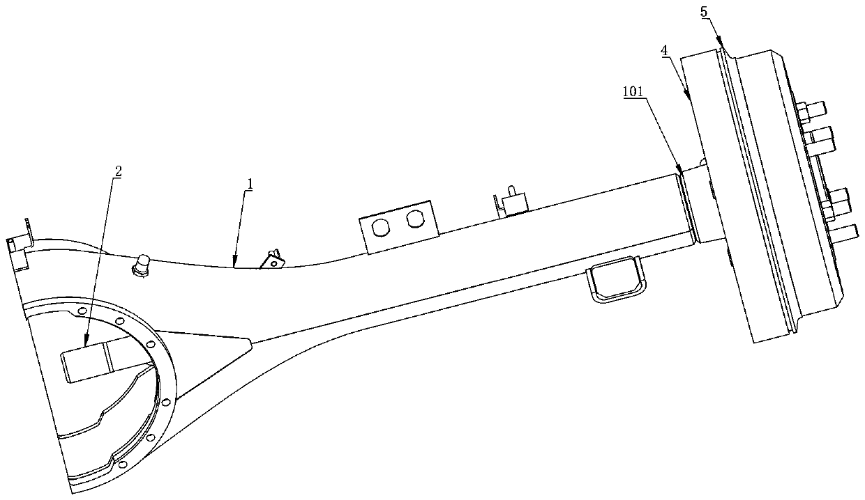
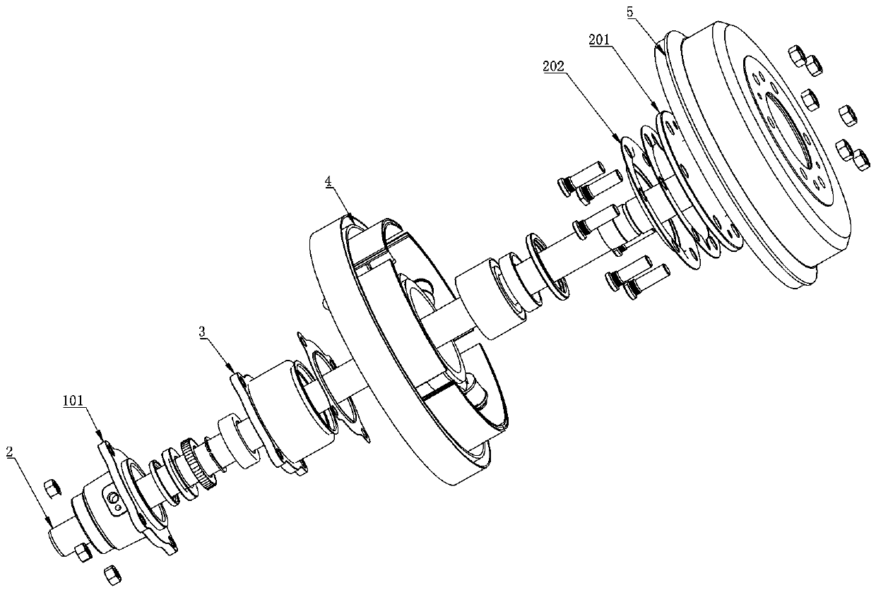
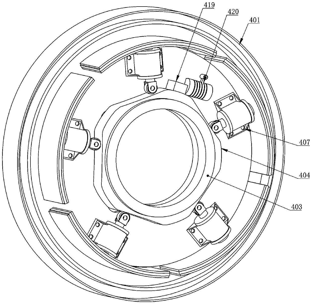
[0020] Specific implementation mode one: combine Figure 1-5 As shown, a high-strength brake hub for heavy-duty vehicles is characterized in that: it includes a main beam of the axle 1, a transmission shaft 2, a bearing seat 3, an electromagnetic rotary brake device 4 and a brake drum 5; the main beam of the axle 1 One end is fixedly welded with a shaft head 101; the bearing seat 3 is installed on the right end of the shaft head 101; the electromagnetic rotary ring brake device 4 is installed on the right side of the shaft head 101; the right end of the transmission shaft 2 is provided with a connection plate 201; A dust cover 202 is installed; the connection plate 201, the dust cover 202 and the brake drum 5 are fixed and locked by bolts; the electromagnetic rotary ring brake device 4 includes a brake chassis 401, a roller 402, a spacer 403, Disk 404, return spring 405 and brake pad 406; shaft head 101, bearing seat 3 and brake chassis 401 are fixed and installed by bolts; dr...


PUM


Abstract

The invention relates to the technical field of drum brake, in particular to a high-strength brake hub for a heavy truck. The brake hub comprises an electromagnetic rotation ring type brake device, during brake, an electromagnetic attraction device pushes a push disc to rotate, multiple brake pieces are pushed to a brake drum at the same time, under the effect of the brake pieces and the brake drum, brake action is achieved, the attaching area of the brake pieces and the brake drum is large, the brake effect is good, and the problem that during traditional drum type braking, the action area ofa brake shoe is small, and the brake effect is not ideal is solved; through control over the current magnitude, torque of a push disc is controlled, the attaching strength of the brake pieces and thebrake drum is controlled, brake strength controllability is finally achieved, control conveying is achieved only through two wires, original parts of a hydraulic pipe, a hydraulic pump and the like are omitted, the advantages of being low in cost, rapid in brake reaction, free of pollution and the like are achieved, and the problem that a traditional brake system adopts oil pressure, the hydraulic cost is high, and the hydraulic oil is leaked to cause pollution is solved.

Description

technical field [0001] The invention relates to the technical field of drum brakes, in particular to a high-strength brake hub for heavy vehicles. Background technique [0002] Compared with disc brakes and drum brakes, drum brakes have a better braking effect. Heavy-duty trucks generally use drum brake systems due to their high inertia during transportation; during the braking process, oil is supplied by a hydraulic pump to drive the piston. Thereby driving the brake shoe to rotate and contact with the inner wall of the brake drum to achieve the effect of braking; there are many brakes in the process of driving, most of which are achieved by contacting the upper part of the brake shoe, and the brake shoe brakes The area is small, and the braking effect is not ideal; the oil pressure, oil pump, oil pipe and other accessories are sealed and installed, the cost is high, and the leakage of hydraulic oil causes pollution; the brake shoes are partially worn, causing unnecessary w...

Claims


Application Information

Patent Timeline
Patent Type & Authority Applications(China)
IPC IPC(8): F16D51/32F16D65/14F16D121/20
CPCF16D51/32F16D65/14F16D2121/20
Inventor 张彦彬
Owner 河北百龙汽车配件股份有限公司
Learn More