Gas combustion rate testing device

A technology of combustion rate and testing device, which is applied in the direction of using combustion for chemical analysis, etc., can solve the problems of no gas combustion rate testing device, and achieve the effect of simple test result collection process, good technical effect, and intuitive experimental process

Active Publication Date: 2019-04-23
应急管理部化学品登记中心 +1
View PDF3 Cites 0 Cited by
  • Summary
  • Abstract
  • Description
  • Claims
  • Application Information

AI Technical Summary

Problems solved by technology

[0003] The technical problem to be solved by this invention is the problem that there is no gas burning rate testing device in the prior art, and a new gas burning rate testing device is provided

Method used


Image

  • Gas combustion rate testing device
  • Gas combustion rate testing device
  • Gas combustion rate testing device

Examples


Embodiment 1

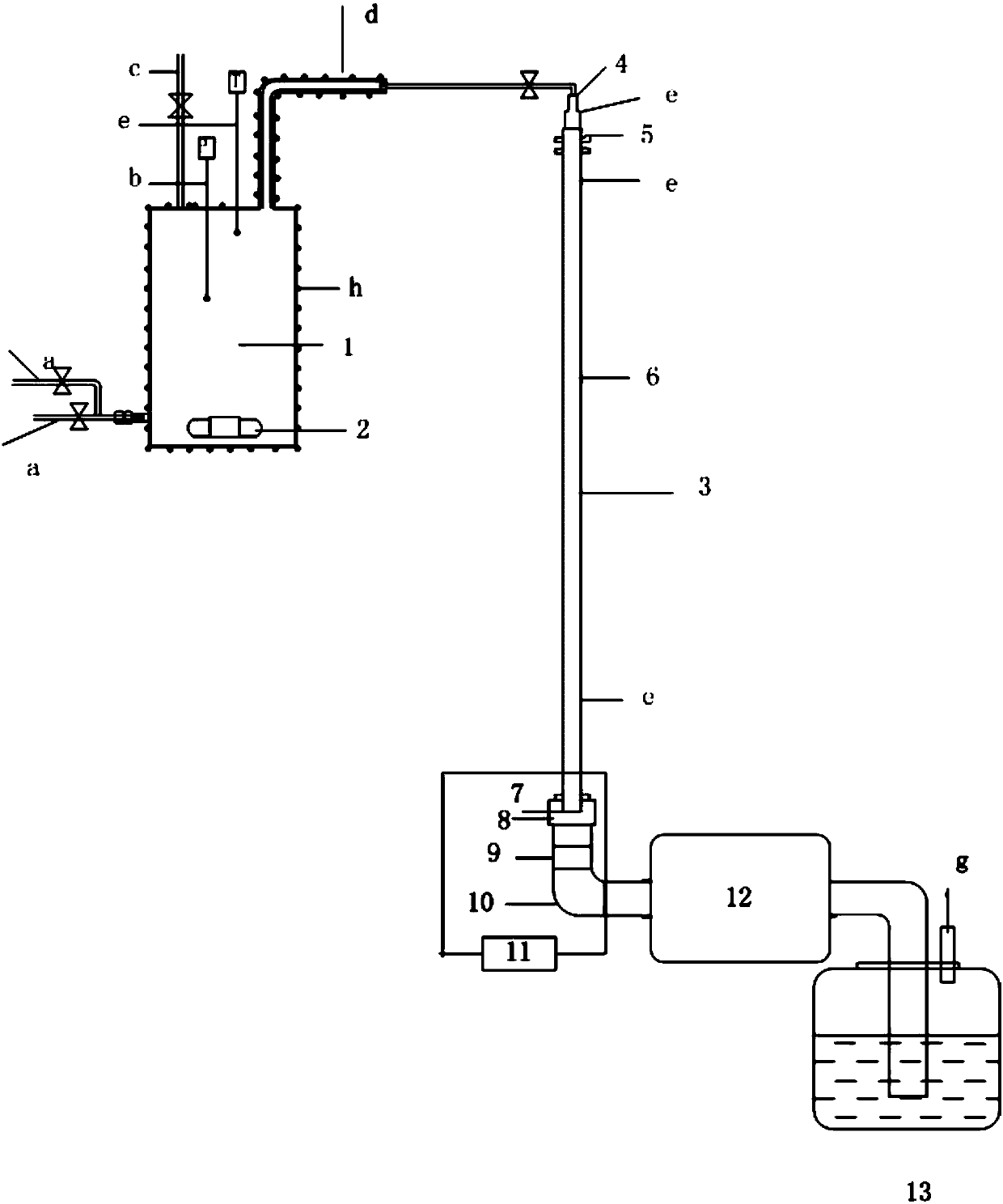
[0038] A gas burning rate testing device, such as figure 1 As shown, it mainly includes a test tube, a mixing container, an ignition system and a gas treatment system. The mixing container is connected to the gas supply tank, the bottom of the container is equipped with magnetic stirring, the outer shell of the container is equipped with a heating layer, and the top of the container is equipped with a pressure test measuring device and Vacuum pump and magnetic stirring are installed at the bottom of the mixing vessel, one end of the purge gas pipeline is connected to the mixing vessel, the other end is connected to the tube inlet of the test tube, the tube inlet is connected to the test tube through a quenching screen, and the quenching screen is installed at both ends of the test tube The outlet of the test tube is connected to the PVC tube through the quenching screen, the other end of the PVC tube is connected to the gas expansion tank, the outlet of the test tube is connect...

Embodiment 2

[0116] Adopt the device of embodiment 1, the mixed gas of certain carbon dioxide and helium, test its combustion rate, concrete implementation process is as follows:

[0117] For a mixture of hydrogen and nitrogen, test its combustion rate. The specific implementation process is as follows:

[0118] 1) The following items should be checked before the experiment starts

[0119] ①Purge the test system with dry air or nitrogen;

[0120] ② Check the gap distance between electrodes and whether it is in the middle;

[0121] ③Select the appropriate outlet pipe diameter.

[0122] 2) The mixture container and all connecting pipes and test pipes are first evacuated to below 10Pa;

[0123] 3) Turn on the magnetic stirring when starting to fill, and fill the mixed gas into the mixing container according to the corresponding partial pressure ratio. The connection should be evacuated every time a new gas is filled, and it should be closed after at least 5 minutes after filling;

[0124...


PUM

PropertyMeasurementUnit
diameteraaaaaaaaaa
diameteraaaaaaaaaa

Abstract

The invention relates to a gas combustion rate testing device mainly used for solving the problem that no gas combustion rate testing device is arranged in the prior art. The gas combustion rate testing device mainly comprises a testing tube, a mixing vessel, an ignition system and a gas treatment system, the mixing vessel is connected with a gas supply tank, a magnetic stirrer is arranged at thebottom of the vessel, a pressure testing and measuring device and a vacuum pump are arranged at the top of the vessel, a vessel shell is provided with a heating layer, one end of a purging gas pipeline is connected with the mixing vessel, the other end of the purging gas pipeline is connected with a tube inlet of the testing tube, the tube inlet is connected with the testing tube through quenchingscreens, quenching screens are mounted at the two ends of the testing tube, an outlet of the testing tube is connected with a polyvinyl chloride tube through the quenching screens, the other end of the polyvinyl chloride tube is connected with a gas expansion tank, the outlet of the test tube communicates with the atmosphere or is connected with the gas treatment system, and the ignition system and a damping hole are formed in the tail end of the testing tube. Through the technical scheme, the problem is well solved, and the gas combustion rate testing device can be used for testing the gas combustion rate.

Description

technical field [0001] The invention relates to a gas combustion rate testing device. Background technique [0002] The flammability classification of gas chemicals is currently mainly classified by two parameters: explosion limit (upper explosion limit, lower explosion limit) and gas pressure. Hazard, so this parameter is introduced into the hazard classification of gas chemicals. The United Nations "Globally Harmonized System of Classification and Labeling of Chemicals" has regarded the gas burning rate as one of the important parameters for judging the gas flammability, but there is no design and development of such gas burning rate test equipment on the market. The gas burning rate provides a fast and effective test device, which can quickly and effectively test the burning rate of the gas, and the experimental process is intuitive, and the data collection process is simple and fast. Contents of the invention [0003] The technical problem to be solved by the present...

Claims


Application Information

Patent Timeline
Patent Type & Authority Applications(China)
IPC IPC(8): G01N31/12
CPCG01N31/12
Inventor 张金梅张玉霞徐鹏飞王康郭璐王亚琴张会光
Owner 应急管理部化学品登记中心
Why Eureka
Try Eureka