Processing simulation display device and processing simulation display method

A display device and display method technology, applied in the direction of comprehensive factory control, program control, instruments, etc., can solve the problems of complexity, inability to master complex tool movement, difficulty in verification operations, etc., and achieve an easy-to-master effect

Active Publication Date: 2021-08-10
MITSUBISHI ELECTRIC CORP
View PDF8 Cites 0 Cited by
  • Summary
  • Abstract
  • Description
  • Claims
  • Application Information

AI Technical Summary

Problems solved by technology

However, in recent years, along with the improvement in functionality and performance of machine tools, machining of parts with complex shapes has been widely performed, and as a result, the machining programs for this purpose tend to be large-scale and complicated.
Therefore, the operator cannot grasp the movement of the complicated tool, and the problem that the verification work becomes difficult becomes serious.

Method used


Image

  • Processing simulation display device and processing simulation display method
  • Processing simulation display device and processing simulation display method
  • Processing simulation display device and processing simulation display method

Examples


Embodiment approach 1

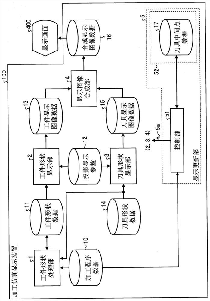
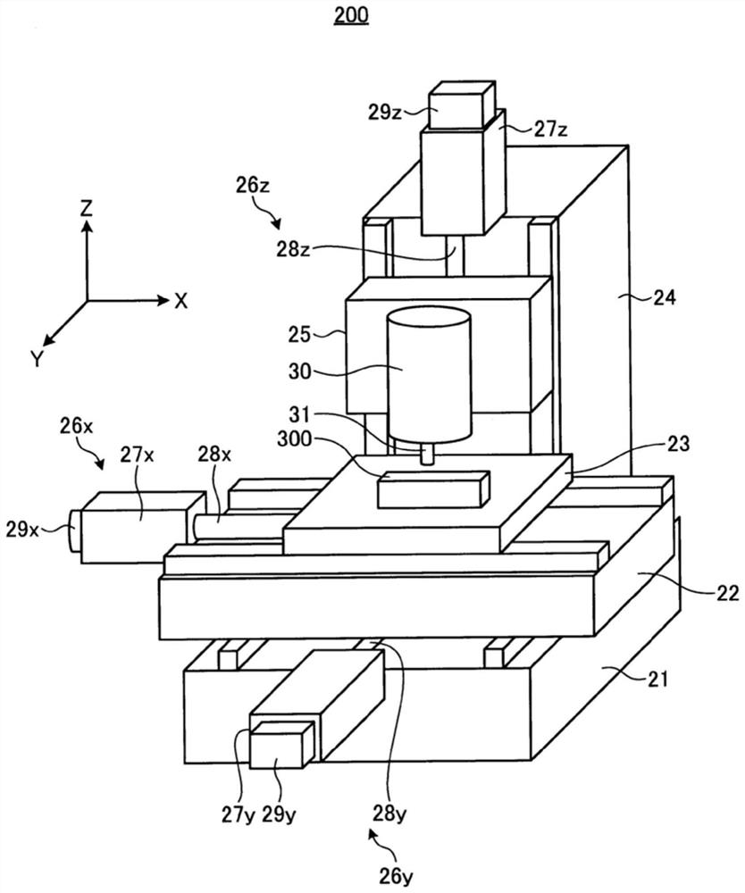
[0023] figure 1 It is a figure which shows the functional structure of the processing simulation display apparatus concerning Embodiment 1 of this invention. figure 2 It is a diagram showing an example of a machine tool and a workpiece to be machined, which are targets of verification work of a machining program. Below, using figure 2 Using figure 1 The function of the processing simulation display device 100 according to Embodiment 1 of the present invention will be described in detail. Hereinafter, the machining simulation display device 100 may be simply referred to as "the machining simulator 100".

[0024] exist figure 2 The appearance of the working machine 200 is shown, and the working machine 200 is an example of a vertical three-axis orthogonal working machine. The working machine 200 has: a stand 21; a saddle 22, which is arranged on the stand 21, and is driven in the y-axis direction; a table 23, which is arranged on the saddle 22; and a column 24, which is ...

Embodiment approach 2

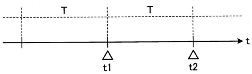
[0054] In Embodiment 1, a configuration example in which the tool display image data 15 generated at the intermediate point is combined with the workpiece display image data 13 generated at the second display update timing t2 was described, but the tool display image generated at the intermediate point The data 15 is combined with the workpiece display image data 13 generated at the first display update timing t1 to obtain the same effect as that of the first embodiment. In Embodiment 2, the structural example which updates the display of the tool display image data 15 based on an intermediate point using the workpiece display image data 13 produced|generated at 1st display update timing t1 is demonstrated. The functional configuration and figure 1 The machining simulators 100 shown are the same, but their operations are different. Use the following Figure 7 , 8 The operation of the machining simulator 100 according to the second embodiment will be described.

[0055] Fig...


PUM


Abstract

The processing simulation display device (100) is a processing simulation display device that displays the shape of the workpiece and the image of the shape of the tool that processes the workpiece on a display screen, and is characterized in that it has a display update unit (5), and the display update unit (5) Command to display the image on the display screen at a change point in the movement path of the tool from the first display update timing at which the image displayed on the display screen is updated to the second display update timing at which a certain display update cycle has elapsed. The image at the position and posture of the change point of the tool shape on the screen is combined with the image of the workpiece shape at the first or second display update timing.

Description

technical field [0001] The present invention relates to a processing simulation display device and a processing simulation display method for simulating processing simulation of a workpiece processed by a working machine. Background technique [0002] When a machine tool driven by a numerical control (Numerical Control: NC) device processes a workpiece to be machined, in order to assist in the verification of the machining program, an image display that simulates the workpiece and the tool installed on the machine tool is used Processing simulation based on the display screen. A CAM (Computer Aided Manufacturing) system that prepares a machining program or an NC device that executes a machining program to control a machine tool often has the machining simulation function. [0003] The operator grasps the processing process of the workpiece and the process of tool movement through animation display by performing machining simulation, thereby verifying machining errors such a...

Claims


Application Information

Patent Timeline
Patent Type & Authority Patents(China)
IPC IPC(8): G05B19/4069
CPCG05B19/4069G05B2219/32351G05B2219/35335Y02P90/02G05B19/402G05B19/4068
Inventor 宫田亮神谷贵志
Owner MITSUBISHI ELECTRIC CORP
Why Eureka
Try Eureka