
Flexible OLED device

A flexible and adhesive layer technology, applied in the field of flexible OLED devices, can solve the problems of reduced impact resistance and easy damage of products, and achieve the effect of improving impact resistance

Active Publication Date: 2019-04-19
WUHAN CHINA STAR OPTOELECTRONICS SEMICON DISPLAY TECH CO LTD
View PDF6 Cites 6 Cited by
  • Summary
  • Abstract
  • Description
  • Claims
  • Application Information

AI Technical Summary

Problems solved by technology

In the manufacturing process of foldable OLED panel modules, in order to make the product light and thin and easy to bend, the thickness of various film materials is reduced as much as possible, but the film material thinning will reduce the impact resistance of the product and the product is easy to be damaged

Method used


Image

  • Flexible OLED device
  • Flexible OLED device
  • Flexible OLED device

Examples


Embodiment Construction

[0025] In order to further illustrate the technical means adopted by the present invention and its effects, the following describes in detail in conjunction with preferred embodiments of the present invention and accompanying drawings.

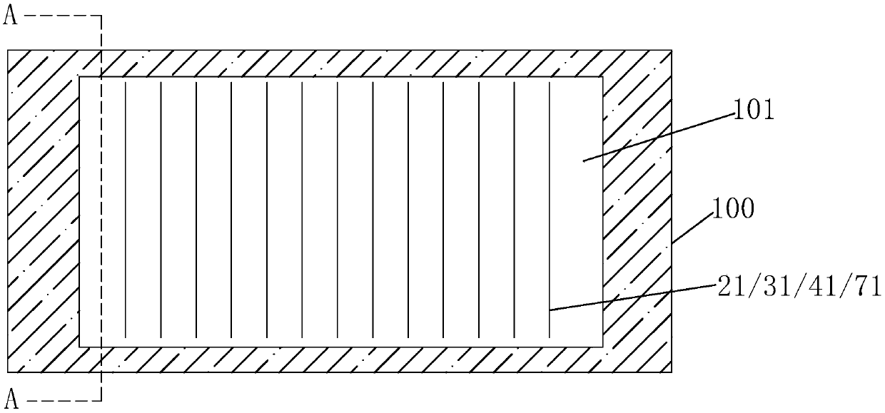
[0026] see figure 1 , the present invention provides a flexible OLED device, comprising: an OLED panel 10 and a cover plate 20 disposed on the OLED panel 10;

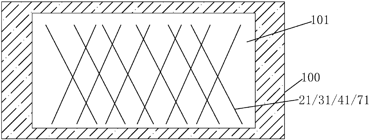
[0027] The cover plate 20 is provided with a plurality of first anti-shock structures 21;

[0028] The first anti-impact structure 21 is used to decompose the impact force received by the flexible OLED device.

[0029] Specifically, the flexible OLED device further includes a cover adhesive layer 30 disposed between the OLED panel 10 and the cover 20; the cover adhesive layer 30 is provided with a plurality of second impact-resistant structures 31 .

[0030] Further, the flexible OLED device further includes an upper protective layer 40 disposed between the OLED panel 10 and the cove...


PUM


Abstract

The invention provides a flexible OLED device. The flexible OLED device comprises an OLED panel and a cover plate arranged on the OLED panel, wherein the cover plate is internally provided with a plurality of first anti-impact structures. The first anti-impact structures cannot damage the original function of a film layer, can effectively decompose an impact force applied to the flexible OLED device, avoids damage to products caused by stress concentration, and improves the impact resistance of the flexible OLED device.

Description

technical field [0001] The invention relates to the field of display technology, in particular to a flexible OLED device. Background technique [0002] Organic Light Emitting Display (OLED) has self-illumination, low driving voltage, high luminous efficiency, short response time, high definition and contrast, nearly 180° viewing angle, wide operating temperature range, and can realize flexible display and With many advantages such as large-area full-color display, it is recognized by the industry as a display device with the most potential for development. [0003] OLED devices generally include: a substrate, an anode disposed on the substrate, a hole injection layer disposed on the anode, a hole transport layer disposed on the hole injection layer, a luminescent material layer disposed on the hole transport layer, a device An electron transport layer on the luminescent material layer, an electron injection layer on the electron transport layer, and a cathode on the electro...

Claims


Application Information

Patent Timeline
IPC IPC(8): H01L27/32G09F9/30
CPCG09F9/301H10K59/12
Inventor 丁峰
Owner WUHAN CHINA STAR OPTOELECTRONICS SEMICON DISPLAY TECH CO LTD
Learn More