wood carving device
A technology of wood and mounting boards, which is applied in the field of engraving machines, can solve problems such as difficulty in movement, deviation of engraving positions, difficulty in meeting needs, etc., and achieve the effect of improving the scope of application, convenient installation and disassembly, and easy maintenance and replacement
- Summary
- Abstract
- Description
- Claims
- Application Information
AI Technical Summary
Problems solved by technology
Method used
Image

Examples
Embodiment 1
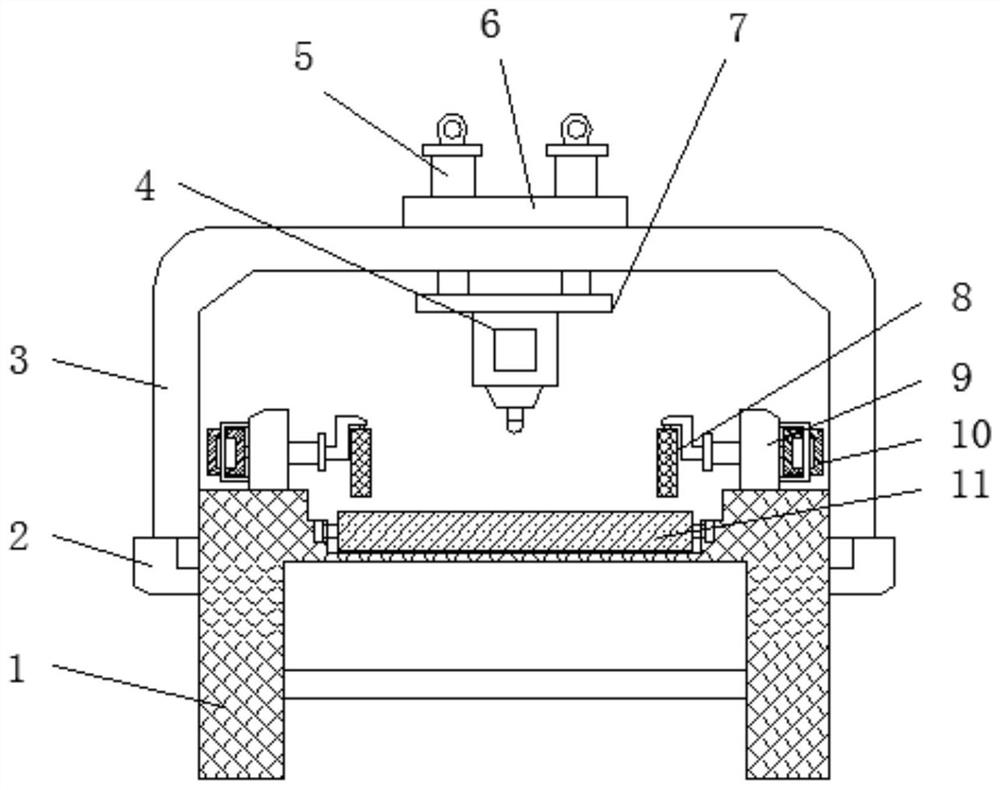
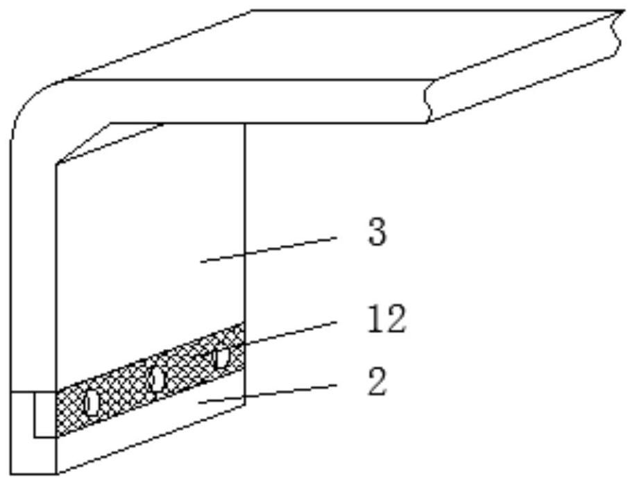
[0025] Example 1, refer to Figure 1-5 , a wood engraving device, comprising a main frame 1, a main frame 3 and a carving device 4, the main frame 3 is located above the main frame 1, the side mounting frames 2 are welded on both sides of the main frame 1, and the main frame 3 is an inverted U-shaped structure , the center of the upper surface of the horizontal end of the main frame 3 is provided with a mounting groove 21, above the mounting groove 21, a mounting plate 6 is clamped by an alignment card 20, an electric push rod 5 is welded on the mounting plate 6, and the lower surface of the mounting plate 6 is The edge is provided with an alignment card slot for use with the alignment card 20. Through the mutual alignment between the alignment card 20 and the alignment card slot, the position of the mounting plate 6 can be more accurate during installation, and there will be no offset. Therefore, the position of the equipment installed on the mounting plate 6 is accurate. The...
Embodiment 2
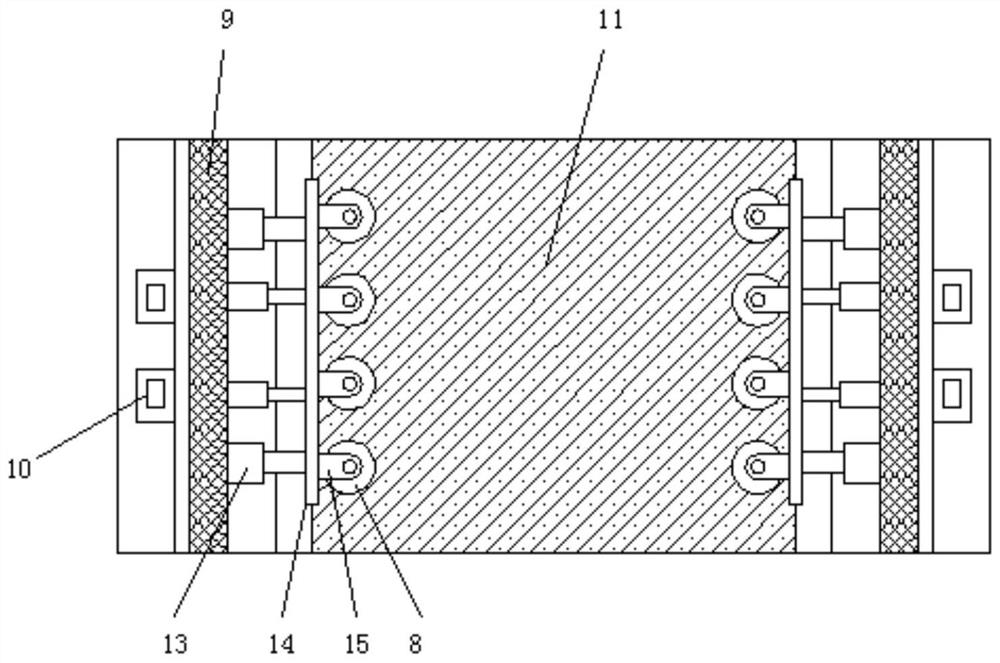
[0026] Example 2, refer to figure 1 , image 3 , a conveyor belt 11 is laid on the center line of the upper surface of the main body bracket 1, a vertical frame 9 is welded on the upper surfaces of both sides of the main body bracket 1, the inner side of the vertical frame 9 is connected with a movable plate 14 through a limit sleeve 13, and the outer side of the vertical frame 9 is fixed by bolts There is a hydraulic cylinder 10. The piston rod of the hydraulic cylinder 10 passes through the vertical frame 9 and is welded to one side of the movable plate 14. The inner side of the movable plate 14 is equidistantly welded with a plurality of roller frames 15. The roller frame 15 is an L-shaped structure. A lateral anti-deflection roller shaft 8 is rotatably connected below the horizontal end of the frame 15 , and two sets of lateral anti-deflection roller shafts 8 are arranged. Through the action of the lateral anti-deviation roller shaft 8, the position of the wood will not b...
Embodiment 3
[0027] Example 3, refer to figure 1 , Figure 3-5 , the upper surface of the main frame 3 is located on both sides of the mounting plate 6 with installation chute 16, the inside of the installation chute 16 is connected with an adjustment bolt 18 through an elastic member 17, one side of the adjustment bolt 18 is welded with a positioning pin 19, the positioning pin One end of 19 penetrates the outer wall of the installation chute 16 and is pinned to the installation plate 6. The two sides of the installation plate 6 are provided with pin holes for use with the positioning pin 19. It is only necessary to slide the adjustment bolt 18 to shrink the elastic member 17, and the positioning pin 19 can be received inside the installation chute 16, so that the installation and disassembly of the device are convenient. The lower engraving device 4 can be disassembled by disassembling the mounting plate 16, so that the engraving device can be easily installed and disassembled, and it i...
PUM
 Abstract
Description
Claims
Application Information
 - R&D
- Intellectual Property
- Life Sciences
- Materials
- Tech Scout
- Unparalleled Data Quality
- Higher Quality Content
- 60% Fewer Hallucinations
Browse by: Latest US Patents, China's latest patents, Technical Efficacy Thesaurus, Application Domain, Technology Topic, Popular Technical Reports.
© 2025 PatSnap. All rights reserved.Legal|Privacy policy|Modern Slavery Act Transparency Statement|Sitemap|About US| Contact US: help@patsnap.com