Robot curved surface motion positioning method and system

A surface movement and positioning method technology, applied in the field of computer vision, can solve problems such as general effects, large positioning errors, and harsh lighting conditions

Active Publication Date: 2019-04-19
TSINGHUA UNIV +1
View PDF10 Cites 13 Cited by
  • Summary
  • Abstract
  • Description
  • Claims
  • Application Information

AI Technical Summary

Problems solved by technology

Chinese patent document CN201110417967 discloses a mobile robot motion attitude estimation method based on machine vision and inertial navigation fusion; A strapdown inertial navigation system / visual odometer combined navigation method uses the fusion of binocular cameras and inertial navigation, and binocular cameras are not effective in matching the surface features of smooth structural parts; Chinese patent document CN201710320077 discloses a method based on The robot positioning and map construction system based on monocular vision and IMU information uses the triangulation method to extract the depth of feature points. When the number of key frame feature points is small, the positioning error is relatively large; Chinese patent document CN201711050182 discloses a mobile robot based on monocular The terminal AR method uses a combination of a monocular camera and an inertial measurement unit, in which the visual motion parameters are obtained by the optical flow method, which is harsh on the lighting conditions and has a large repeat positioning error; Chinese patent document CN201711077826 discloses a visual inertial navigation information based The fusion positioning method and system adopts the combination method of RGB-D camera and inertial measurement unit, only uses the depth value of the feature point, and the effect is general in the smooth surface position positioning
[0005] The technology disclosed above is not suitable for long-term position positioning and attitude positioning of industrial robots on the surface of large structural parts or large equipment

Method used


Image

  • Robot curved surface motion positioning method and system
  • Robot curved surface motion positioning method and system
  • Robot curved surface motion positioning method and system

Examples


Embodiment Construction

[0079] The technical solution of the present invention will be clearly and completely described below in conjunction with the accompanying drawings and embodiments:

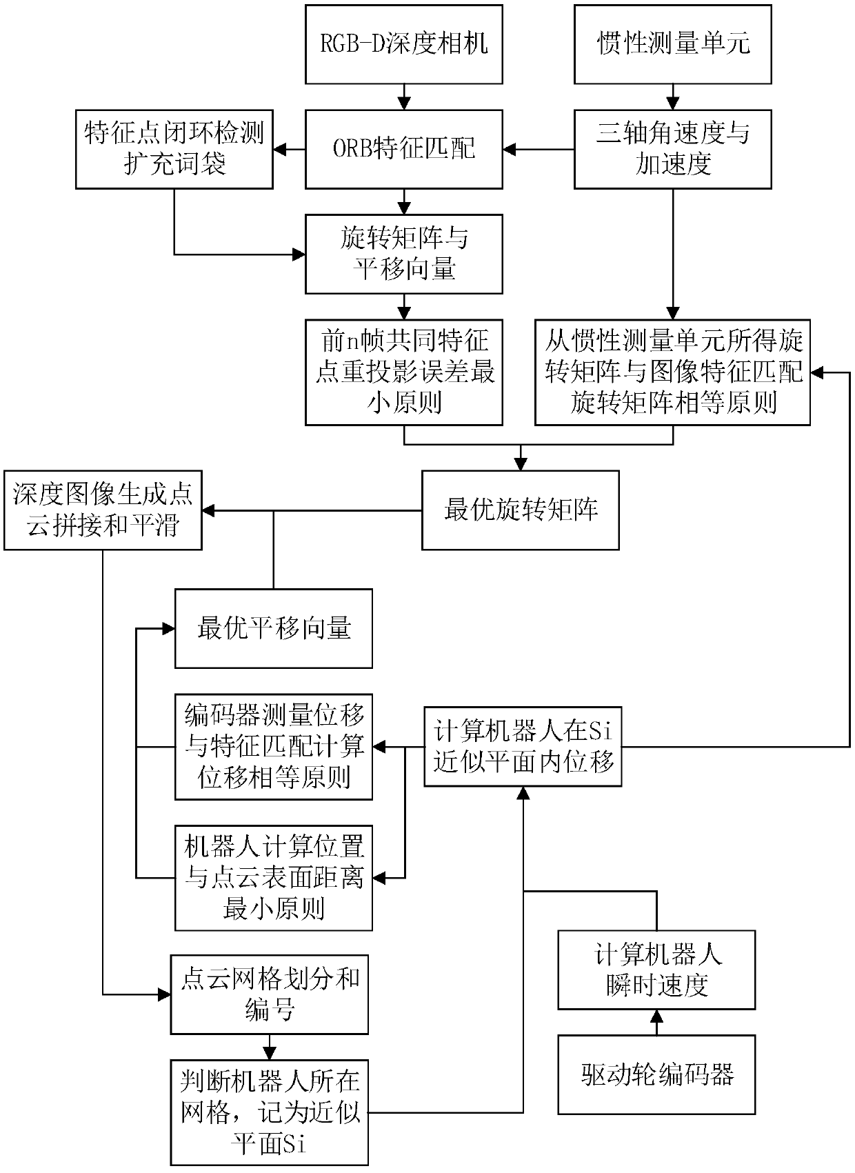
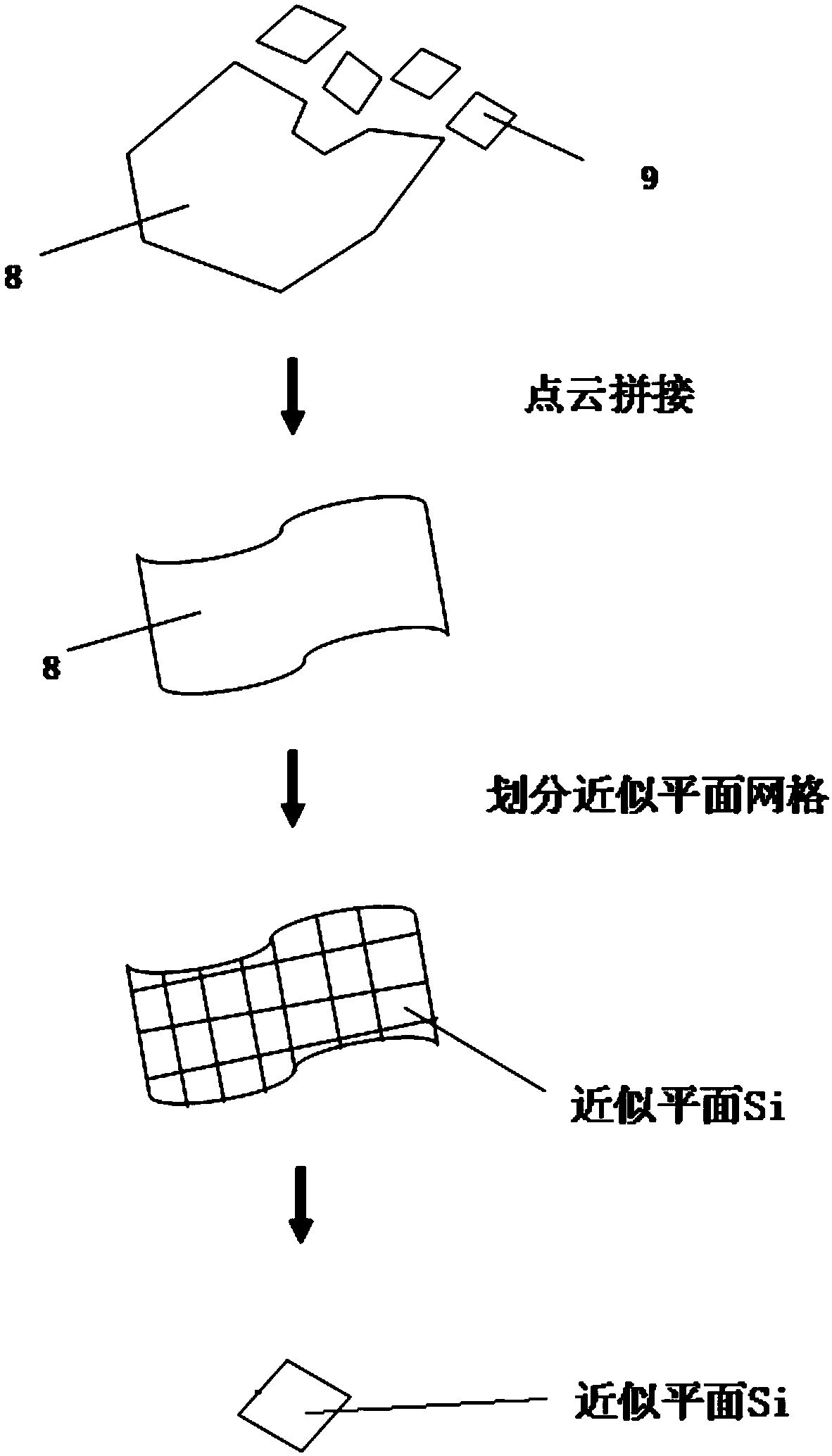
[0080] A multi-sensor information fusion positioning method for robot surface movement, such as figure 1 As shown, the method includes the following steps:

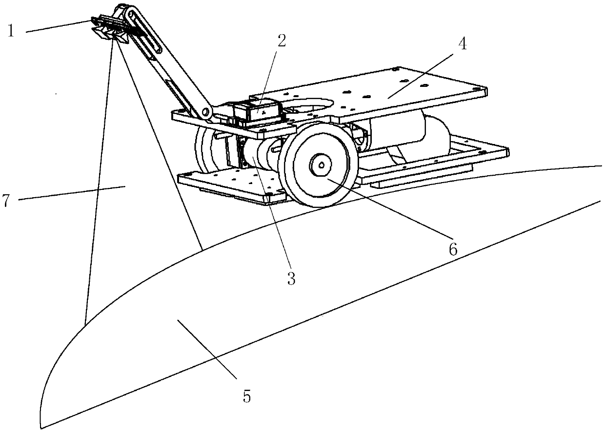
[0081] 1) Establish a robot surface motion positioning system and define a coordinate system: the robot surface motion positioning system includes a robot and an auxiliary mechanism installed on the robot, and the auxiliary mechanism includes an RGB-D camera, an inertial measurement unit (IMU), an incremental encoding device, an adsorption mechanism and a motion mechanism, the adsorption mechanism is used to adsorb on the surface of an object, and the motion mechanism is used to drive the robot to move; the coordinate system includes a space inertial coordinate system, an RGB-D camera coordinate system, and an image plane coordinate system , Robot coordinat...


PUM


Abstract

The invention discloses a robot curved surface motion positioning method and system. According to the method, an RGB-D depth camera is adopted for acquiring a color image and a depth image of a curvedsurface of the position in front of a robot during movement, a triaxial angular velocity value and a triaxial acceleration value of an inertial measurement unit are recorded, a rotation matrix and atranslation vector obtained through feature matching are optimized, and point cloud registration is conducted according to the depth image; and a registered point cloud is divided into approximately planar grids, the robot motion velocity is calculated according to an output value of a wheel encoder, and the robot displacement in the grid is calculated through a plane odometer method. Through theadopted depth point cloud registration method, all robot curved surface motion scene information is fully utilized, the real-time speed of the robot is obtained through the encoder, the position positioning precision and the posture positioning precision of the robot during movement on the curved surface for a long time are improved, and the anti-interference ability is high.

Description

technical field [0001] The invention relates to a computer vision technology, in particular to a robot curved surface motion positioning method and a motion positioning system thereof. Background technique [0002] With the development of robot technology and the increase of labor costs, robots can replace manual cleaning of high-rise building exterior walls, surface inspection and maintenance of large structural parts, welding and inspection of large equipment such as large ships, which can improve production efficiency, reduce manufacturing costs, and reduce labor costs. Labor intensity and operational risk. The industrial wall-climbing robot consists of a working platform and a mobile chassis that can absorb wall movement, and can move and work in dangerous environments such as vertical walls. The industrial wall-climbing robot needs to adjust the angle and position of the working unit according to its own posture and position information, such as welding, grinding, surf...

Claims


Application Information

Patent Timeline
Patent Type & Authority Applications(China)
IPC IPC(8): B25J9/16B25J5/00
CPCB25J5/007B25J9/1664B25J9/1694B25J9/1697
Inventor 张文孙振国陈咏华张文东陈强
Owner TSINGHUA UNIV
Why Eureka
Try Eureka