
Continuous ultrasonic cleaning device

A cleaning device and ultrasonic technology, applied in the direction of cleaning flexible items, cleaning methods and utensils, cleaning methods using liquids, etc., can solve the problems of pauses and gaps in the processing process, poor compatibility, and insufficient cleaning effect of roller brushes.

Inactive Publication Date: 2019-04-19
福州东旭光电科技有限公司 +2
View PDF10 Cites 1 Cited by
  • Summary
  • Abstract
  • Description
  • Claims
  • Application Information

AI Technical Summary

Problems solved by technology

Among them, the roller brush cleaning can be well combined with the glass conveying, so that the glass can be continuously conveyed without interruption, but the cleaning effect of the roller brush is not thorough enough; the basket-type ultrasonic cleaning device needs to clamp the glass from the continuous conveying processing line Take it out and transport it to the basket of the basket-type ultrasonic cleaning device, then lower the basket into the water tank for ultrasonic cleaning, after the cleaning is completed, the basket rises, then take out the glass and transport it back to the production line, and continue the subsequent processing, transportation and other processes
[0003] Since glass is generally conveyed continuously during the processing process, this will cause pauses and gaps in the glass processing process, resulting in discontinuous processes, poor compatibility with other processing processes, and increased operations such as glass clamping and handling. decrease productivity

Method used


Image

  • Continuous ultrasonic cleaning device
  • Continuous ultrasonic cleaning device
  • Continuous ultrasonic cleaning device

Examples


Embodiment Construction

[0043] Specific embodiments of the present invention will be described in detail below in conjunction with the accompanying drawings. It should be understood that the specific embodiments described here are only used to illustrate and explain the present invention, and are not intended to limit the present invention.

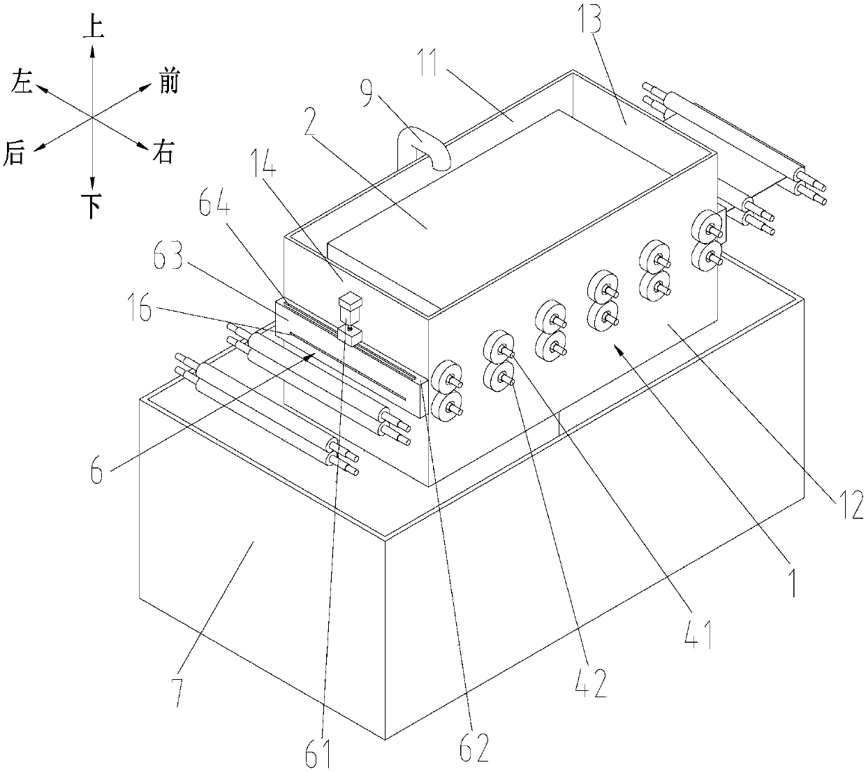
[0044] In the present invention, in the case of no contrary description, the used orientation words such as "up, down, left, right, front, back" such as Figure 1-Figure 4 marked in.

[0045] Such as Figure 1-Figure 4 As shown, the specific embodiment of the present invention provides a continuous ultrasonic cleaning device, comprising a water tank 1, an upper ultrasonic generator 2, a lower ultrasonic generator 3, a plurality of delivery rollers 4, an inlet gate 5, an outlet gate 6, and a delivery roller The two ends of 4 are rotatably installed on the left side wall 11 and the right side wall 12 of the water tank 1, the conveying roller 4 is used to convey ...


PUM


Abstract

The invention relates to a continuous ultrasonic cleaning device. The continuous ultrasonic cleaning device comprises a water box, an upper ultrasonic generator, a lower ultrasonic generator, a plurality of conveying rollers, an inlet gate and an outlet gate; the two ends of the conveying rollers are rotatably installed on the left side wall and the right side wall of the water box, and the conveying rollers are used for conveying glass; the upper ultrasonic generator and the lower ultrasonic generator are arranged in the water box and located above and below the conveying rollers correspondingly; the front side wall of the water box is provided with an inlet for allowing the glass to enter, and the rear side wall of the water box is provided with an outlet for discharging the glass; and the inlet gate is used for closing and opening the inlet, and the outlet gate is used for closing and opening the outlet. The continuous ultrasonic cleaning device can conduct ultrasonic cleaning on the glass under the continuous glass conveying situation and can be compatible and be combined with glass continuous conveying or glass roller brushing of other glass processing procedures, so that themachining process is continuous and ceaseless, additional clamping, moving and other operation are not needed, and the working efficiency is improved.

Description

technical field [0001] The invention relates to the field of electronic glass manufacturing and processing, in particular to a continuous ultrasonic cleaning device. Background technique [0002] At present, electronic glass products such as substrate glass are generally cleaned by roller brushes arranged continuously along the glass conveying direction, or by basket-type ultrasonic cleaning devices. These two cleaning methods have their own advantages. Among them, the roller brush cleaning can be well combined with the glass conveying, so that the glass can be continuously conveyed without interruption, but the cleaning effect of the roller brush is not thorough enough; the basket-type ultrasonic cleaning device needs to clamp the glass from the continuous conveying processing line Take it out and transport it to the basket of the basket-type ultrasonic cleaning device, then lower the basket into the water tank for ultrasonic cleaning, after the cleaning is completed, the b...

Claims


Application Information

Patent Timeline
IPC IPC(8): B08B3/12B08B13/00B08B11/04
CPCB08B3/123B08B11/04B08B13/00
Inventor 李远胡恒广宋述远
Owner 福州东旭光电科技有限公司
Learn More