
Method and apparatus for controlling jet dispensing by displacement measurement

A technology of displacement and injector, which is applied in the direction of injection device, injection device, printed circuit manufacturing, etc., and can solve problems such as poor contact and short circuit

Pending Publication Date: 2019-04-16
MYCRONIC
View PDF3 Cites 9 Cited by
  • Summary
  • Abstract
  • Description
  • Claims
  • Application Information

AI Technical Summary

Problems solved by technology

Too small a volume of deposition medium or poorly shaped or positioned deposits can result, for example, in dry joints or loose components, while too large a volume of deposition medium can result in contamination, for example by solder balls or by adhesives or underfills. Short circuit caused by poor contact

Method used


Image

  • Method and apparatus for controlling jet dispensing by displacement measurement
  • Method and apparatus for controlling jet dispensing by displacement measurement
  • Method and apparatus for controlling jet dispensing by displacement measurement

Examples


Embodiment Construction

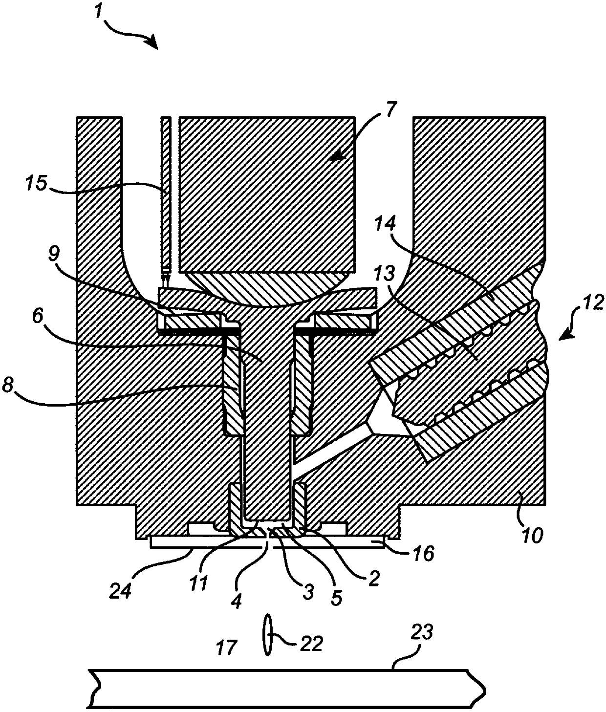
[0100] refer to figure 1 , shows a schematic diagram of an injector according to an embodiment of the technology.

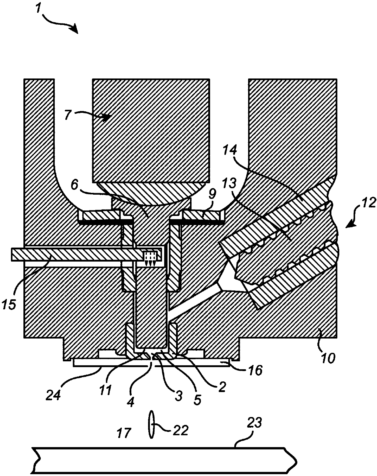
[0101] The injector 1 comprises an assembly housing 10 and an impact device which in this embodiment may comprise a piezoelectric actuator 7 and a plunger or piston 6 operatively connected to the piezoelectric actuator 7 . The plunger 6 is axially movable while slidably extending through a bore in the bushing 8 . A cup spring 9 may be provided to elastically balance the plunger 6 on the assembly housing 10 and to provide a preload for the piezoelectric actuator 7 . A control unit (not shown) may intermittently apply a driving voltage to the piezoelectric actuator 7 to intermittently extend it according to solder pattern printing data, thereby reciprocating the plunger 6 relative to the assembly housing 10 .

[0102] Furthermore, the injector 1 may comprise a spray nozzle 2 operatively directed towards a substrate 23 onto which droplets 22 of the viscous medium ...


PUM


Abstract

A method for jetting a viscous medium onto a substrate (23) is disclosed. The method comprises providing (110) viscous medium to a jetting chamber (5) of an ejector (1), operating (120) an impacting device (6, 7) to impact a volume of the viscous medium in the chamber such that viscous medium is jetted through a nozzle (4), connected to the chamber, towards the substrate, and monitoring (130) a displacement of the impacting device during the impact. An ejector and a system comprising such an ejector and a control unit (32) is also disclosed. The monitoring of the displacement allows for the operation of the impacting device to be controlled accordingly, thereby providing for an improved control of the jetting process.

Description

technical field [0001] The invention disclosed herein relates to jetting a viscous medium onto a substrate. In particular, the invention relates to a method as well as an injector and a system in which the displacement of the impact device of the injector is monitored. Background technique [0002] Sprayers and methods are known in the art for ejecting droplets of a viscous medium or fluid, such as solder paste, flux or adhesive, onto a substrate such as a printed wiring board (PWB), thereby forming Deposits attached to the substrate. Such injectors generally consist of a chamber for containing a volume of viscous medium prior to its spraying, a spray nozzle communicating with the nozzle space, and an impingement for impinging and spraying the viscous medium from the chamber in the form of droplets through the nozzle device. Furthermore, a feeder can be used to feed the medium into the nozzle space. The amount or volume of deposited viscous medium at different locations ...

Claims


Application Information

Patent Timeline
IPC IPC(8): H05K3/12B05B1/08B05B12/08
CPCH05K3/1241H05K3/14B05B1/08B05B12/10B05D1/02B05B1/083B05B12/08H05K3/125B05C11/1034B05C5/0225B05C11/1007B05D1/26B05B1/3046B05B12/082
Inventor D.布雷卫马克
Owner MYCRONIC
Learn More