Handle device

A technology for handles and door handles, applied in signal devices, sealing devices, transportation and packaging, etc., to achieve the effect of reducing light intensity and reducing light intensity

Active Publication Date: 2019-04-16
HUF HULSBECK & FURST GMBH & CO KG
View PDF9 Cites 2 Cited by
  • Summary
  • Abstract
  • Description
  • Claims
  • Application Information

AI Technical Summary

Problems solved by technology

With such door handles it is difficult to achieve front lighting in or at the door handle

Method used


Image

  • Handle device
  • Handle device
  • Handle device

Examples


Embodiment Construction

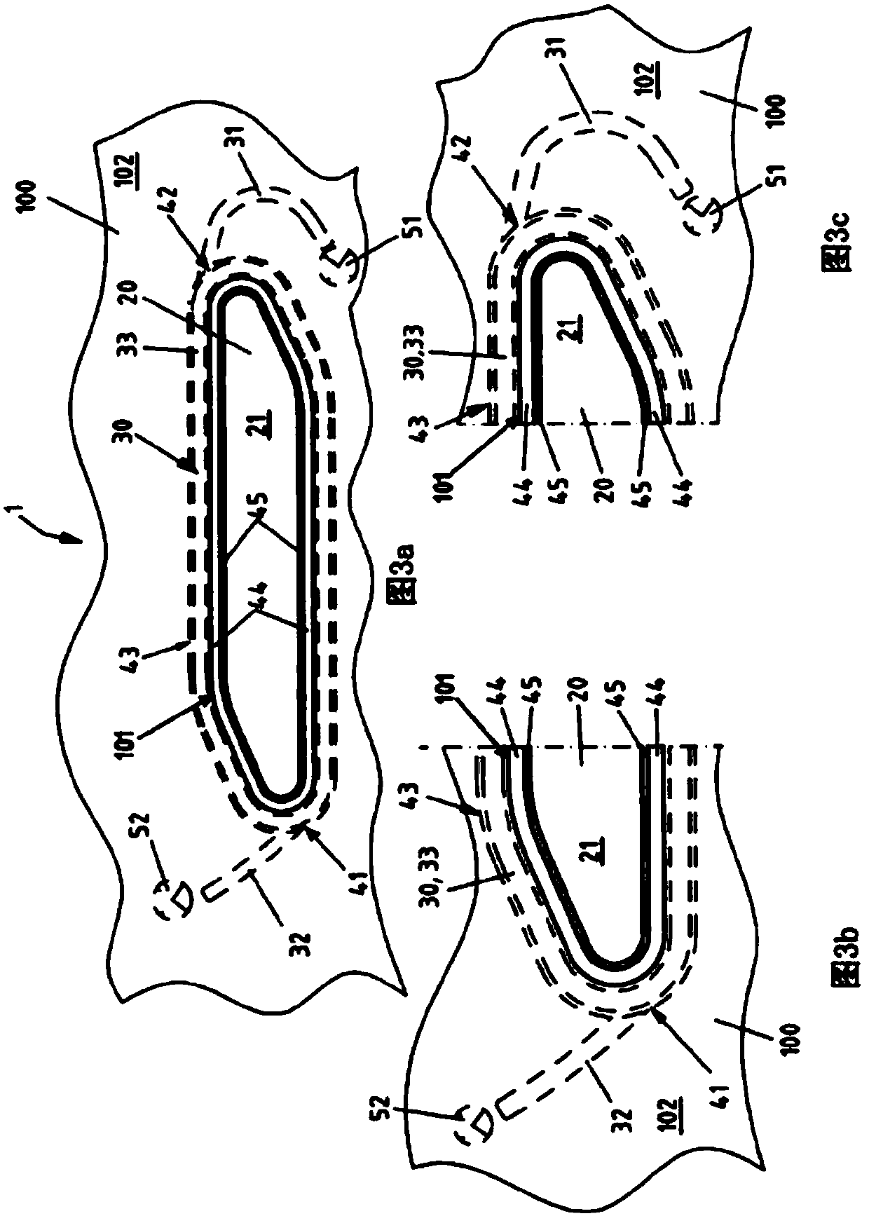
[0042] In the figures, the same reference signs are used for the same technical features even for different exemplary embodiments.

[0043] figure 1 with figure 2 A handle arrangement 1 according to the invention for a movable part 100 of a motor vehicle in the form of a motor vehicle door 100 is shown. The handle device 1 is designed with a base part 10 in which a receptacle 11 for a door handle 20 is formed. The base member 10 can be positioned at a hole 101 in the movable part 100 by the receiving slot 11 . The door handle 20 is movably mounted on the base member 10 , especially in the cavity 11 . The door handle 20 is a so-called flush door handle 20, which is in the figure 1 In the rest position I shown it is housed in the housing 11 so as to close the hole 101 in the movable part 100 with the outer surface 21 of the door handle 20 substantially flush with the outer surface 102 of the movable part 100 . in such as figure 2 In the operating position II shown, the d...


PUM


Abstract

The invention relates to a handle device (1) for a movable part (100), in particular a motor vehicle door (100) of a motor vehicle, which is implemented with a carrier element (10), wherein a receptacle (11), which can be arranged on an opening (101) in the removable part (100), is formed on the carrier element (10), wherein an in particular surface-flush door handle (20) for actuating the movablepart (100) is movably mounted on the carrier element (10), and wherein the door handle (20) is formed in such a way that a front-side gap (S) is adjustable between the opening (101) in the movable part (100) and the door handle (20). To this end, according to the invention, an optical fiber (30) is arranged on the carrier element (10), in order to illuminate the door handle (20) indirectly through the gap (S).

Description

technical field [0001] The invention relates to a handle arrangement for a moving part of a motor vehicle, in particular a door of a motor vehicle, according to the preamble of the independent device claim, having a base part, wherein a recess is formed on the base part, which can be arranged on the moving part At the hole in the base part, especially in the receptacle, a door handle for operating the movable part is movably mounted on the base part, especially flush with the surface, and the door handle is designed so that the hole in the movable part coincides with the door handle The front gap can be adjusted. The invention also relates to a method for illuminating a particularly flush door handle for moving parts of a motor vehicle, in particular a motor vehicle door, according to the preamble of the independent method claim. Background technique [0002] There are various ideas for producing front lighting in motor vehicles. In this case, on the one hand, a light sour...

Claims


Application Information

Patent Timeline
Patent Type & Authority Applications(China)
IPC IPC(8): E05B85/10B60Q1/26E05B17/10
CPCB60Q1/2669E05B17/10E05B85/103E05B85/107F21S43/237F21S43/241F21S43/245F21S43/249B60J10/86E05Y2900/531
Inventor 伯恩德·赖芬博格迈克尔·莱茵
Owner HUF HULSBECK & FURST GMBH & CO KG
Why Eureka
Try Eureka