Tool for installing or removing wire thread inserts and method of manufacture

A technology for wire threaded inserts and tools, applied in the manufacture of tools, screwdrivers, hand-held tools, etc., can solve the problems of material fatigue, maintenance costs, shorten tool life, etc., and achieve the effect of reducing mechanical stress

Active Publication Date: 2021-07-23
BOLLHOFF VERBINDUNGSTECHNIK GMBH
View PDF9 Cites 0 Cited by
  • Summary
  • Abstract
  • Description
  • Claims
  • Application Information

AI Technical Summary

Problems solved by technology

This repetitive, almost cyclical loading results in material fatigue and material failure in the radial recesses, which detrimentally shortens tool life and creates maintenance costs
For this reason, after using the tool for a period of time, this mechanical load causes damage to the spindle body adjacent to the contact end where the insert is mounted

Method used


Image

  • Tool for installing or removing wire thread inserts and method of manufacture
  • Tool for installing or removing wire thread inserts and method of manufacture
  • Tool for installing or removing wire thread inserts and method of manufacture

Examples


Embodiment Construction

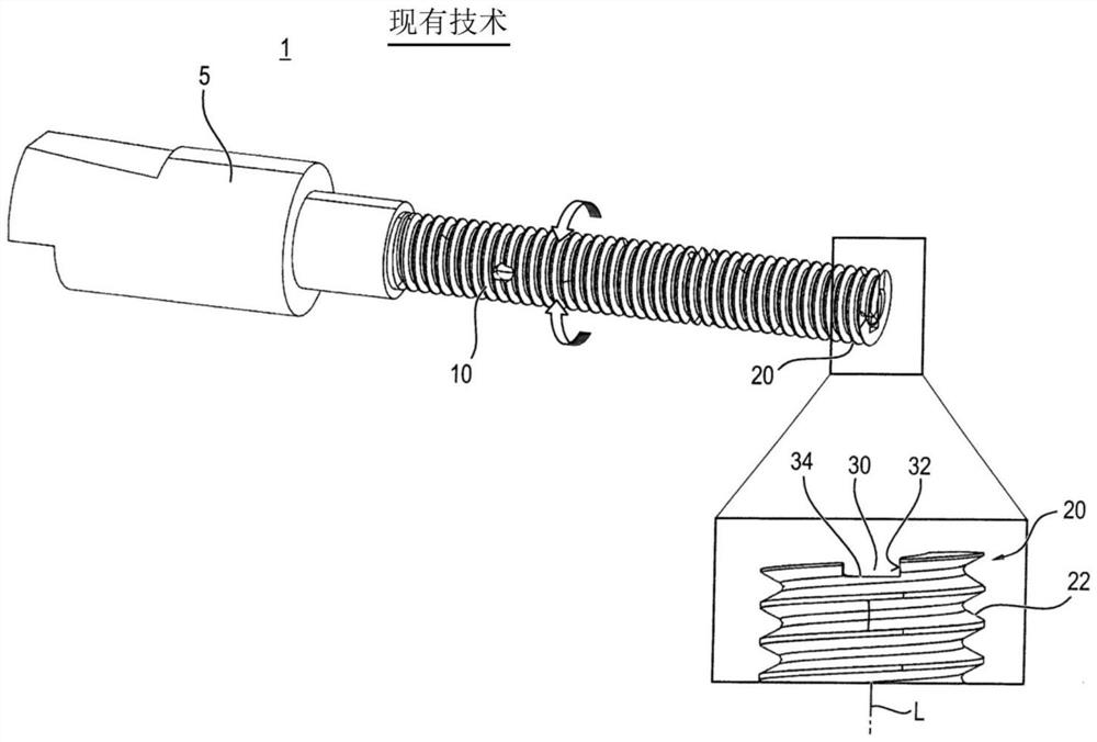
[0028] As mentioned above, various tools for installing or removing wire thread inserts are known in the prior art. figure 1 An example of such a tool 1 is shown. The tool 1 comprises a spindle body 10 which can be rotated automatically and / or manually by means of a drive 5 . figure 1 The drive part 5 is shown which can be fastened in a suitable chuck of the drive. For turning the tool 1 manually, a lever or arm (not shown) is preferably provided transverse to the longitudinal axis L of the tool 1 .

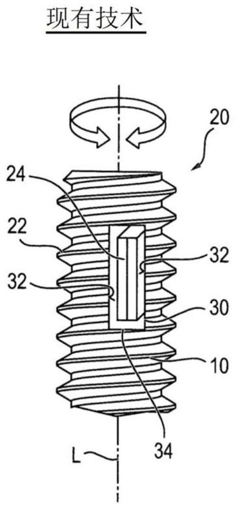
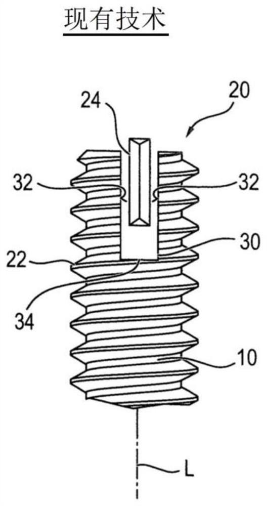
[0029] The spindle body 10 has a seat 20 for a wire threaded insert (not shown) at an end opposite to the drive portion 5 . Seat 20 can be in figure 1 See the partial enlargement in Fig.

[0030] The seat 20 includes threads 2 for turning or screwing on a wire thread insert, or a non-threaded face (not shown) for inserting a wire thread insert.

[0031] In the spindle body 10 there is generally provided an axial opening (not shown) in which a mounting insert (also not shown)...


PUM


Abstract

The invention relates to a tool (1) for installing or removing a wire thread insert and a method for its manufacture. The spindle body inserted in the tool (1) has a radial recess (30) through which the engagement end (24) of the mounting blade engages the wire thread insert. The radial recess (30) has a curved circumferential profile or at least one relief notch (40) for mechanical tension relief in the spindle body (10).

Description

technical field [0001] The invention relates to a tool for installing and removing wire thread inserts and a method of manufacturing the same. Background technique [0002] Various tools are known in the art for installing or removing wire thread inserts. These tools include a spindle body, usually with a drive portion and a seat portion with threads for fastening onto a wire threaded insert. The mounting blade is arranged inside the main shaft body. The mounting blade is of elongated construction with a central pivot point. This intermediate pivot point is also usually the attachment point for mounting the blade formed by a pin riveted into the spindle body. The contact end is arranged at the end where the blade is mounted and engages in the wire thread. Typically, a spring is arranged at the other end where the blade is mounted such that the contact end is spring biased in the engaged position in the wire thread insert. [0003] EP0153266, EP0153267, EP0153268B1, EP06...

Claims


Application Information

Patent Timeline
Patent Type & Authority Patents(China)
IPC IPC(8): B25B27/14
CPCB25B27/143B25B27/14B25B23/141
Inventor 安德烈亚斯·马克思克斯
Owner BOLLHOFF VERBINDUNGSTECHNIK GMBH
Why Eureka
Try Eureka