
Multi-lead-screw synchronous motor lifting rod

A lifting rod and lead screw drive technology, applied in the direction of lifting devices, etc., can solve the problems of increasing motor power consumption, large friction area, easy wear of nuts, etc.

Inactive Publication Date: 2016-12-21
铁岭长天机电有限责任公司
View PDF6 Cites 6 Cited by
  • Summary
  • Abstract
  • Description
  • Claims
  • Application Information

AI Technical Summary

Problems solved by technology

[0004] The problem of the multi-screw mechanical lifting rod in the above-mentioned prior art when lifting is that since the outer circumference of the bottom screw and the inner tube screw is formed with an axial plane, when the lifting rod is raised or lowered as a whole, there is no contact with the bottom screw. The nut on the annular lower sleeve that the lead screw and the inner pipe lead screw match is easy to wear, and long-term use will cause the screw thread of the nut to fail, and the normal lifting operation cannot be completed; And the inner tube screw slides up and down through the bow-shaped pin block installed at the lower end of the nozzle and the axial plane of the adjacent inner tube screw and bottom screw. When sliding, the friction area is large and increases Motor power consumption

Method used


Image

  • Multi-lead-screw synchronous motor lifting rod
  • Multi-lead-screw synchronous motor lifting rod
  • Multi-lead-screw synchronous motor lifting rod

Examples


Embodiment Construction

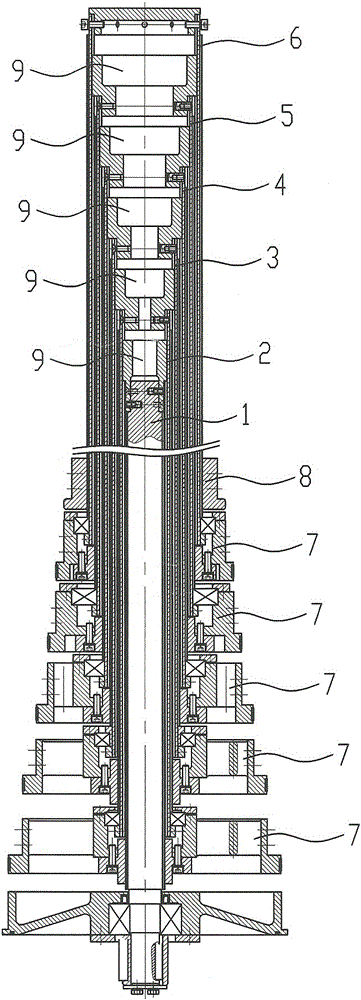
[0018] see figure 1 - Figure 9 , the multi-screw synchronous electric lifting rod of the present invention has a tube body (not shown in the figure) and a tube body screw drive device, the screw drive device includes a plurality of round tube screw screws 1, 2, 3, 4 , 5, 6, the innermost round tube screw is the bottom screw 1, the outermost round tube screw is the top tube screw 6, and the rest of the round tube screw is the inner tube screw 2, 3 , 4, 5, the lower ends of the bottom screw 1 and the inner tube screw 2, 3, 4, 5 are respectively connected with an annular lower sleeve 7, and the lower end of the top tube screw 6 is engaged with a nut 8, The upper ends of the bottom screw 1 and the inner tube screw 2, 3, 4, 5 are connected with an annular upper sleeve 9, and the outer peripheral wall of the annular upper sleeve 9 has a guide key 10 along the axial direction; The inner wall of the inner tube screw 2 , 3 , 4 , 5 and the jack screw 6 has an axial guide groove 11 ma...


PUM


Abstract

The invention discloses a multi-lead-screw synchronous motor lifting rod. The multi-lead-screw synchronous motor lifting rod comprises a pipe body and a lead screw driving device of the pipe body. The lead screw driving device comprises a plurality of round pipe lead screws. The innermost round pipe lead screw is a bottom lead screw, the outermost round pipe lead screw is a top pipe lead screw, and the rest of round pipe lead screws are inner pipe lead screws. The lower end of the bottom lead screw and the lower ends of the inner pipe lead screws are connected with ring-shaped lower sleeves correspondingly. The lower end of the top pipe lead screw is connected with a nut in an engaged mode. The upper end of the bottom lead screw and the upper ends of the inner pipe lead screws are connected with ring-shaped upper sleeves. The outer circumferential walls of the ring-shaped upper sleeves are provided with guiding keys in the axial direction. The inner walls of the inner pipe lead screws and the inner wall of the top pipe lead screw are provided with axial guiding grooves matched with the guiding keys. The bottom lead screw and the inner pipe lead screws are matched with the adjacent inner pipe lead screws and the top pipe lead screw through the keys and the grooves, axial planes do not needed to be machined on the pipe wall of the bottom lead screw and the pipe walls of the inner pipe lead screws, nuts on the ring-shaped lower sleeves are not prone to abrading, so that the normal lifting operation of the multi-lead-screw synchronous motor lifting rod can be ensured.

Description

technical field [0001] The invention relates to a multi-screw synchronous electric lifting rod. Background technique [0002] In the prior art, the invention patent declared by the applicant in July 2015 and authorized has been disclosed. The patent name is "a multi-screw mechanical lifting rod", the authorized announcement number is CN204981006U, and the authorized announcement date is 2016.01.20 . [0003] A multi-screw mechanical lifting rod in the above-mentioned prior art has a tube body and a screw drive device for the tube body. The tube body has a plurality of circular tubes whose axes are on the same straight line and whose diameters range from large to small. There are axial guide keys on the outer wall of the round tube, and guide grooves on the inner circumference of the upper sleeve of the round tube; the screw drive device has multiple round tube screw screws inside the round tube, and the innermost round tube screw is the bottom screw , the outermost round t...

Claims


Application Information

Patent Timeline
IPC IPC(8): B66F3/10
CPCB66F3/10
Inventor 朱喜成张静晓隋玉春司宝库张建伟石阳
Owner 铁岭长天机电有限责任公司
Learn More