
Emitter structure of double-layer amorphous silicon doped layer solar cell and preparation method thereof

A technology for solar cells and amorphous silicon layers, applied in circuits, photovoltaic power generation, electrical components, etc., can solve problems such as low transmittance, inability to achieve high conversion efficiency of HJT cells, poor conductivity, etc., to increase conductivity, The effect of improving photoelectric conversion efficiency

Inactive Publication Date: 2019-04-16
SUZHOU AIKANG LOW CARBON TECH INST
View PDF4 Cites 6 Cited by
  • Summary
  • Abstract
  • Description
  • Claims
  • Application Information

AI Technical Summary

Problems solved by technology

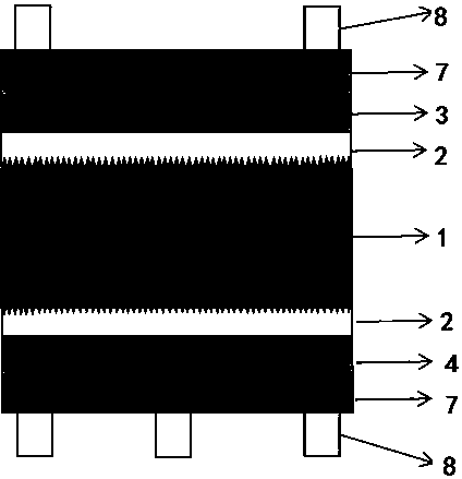
[0005] see figure 1 , the existing technology is a single-layer amorphous silicon doped layer P, wherein the doping ratio of B2H6 doping is 1%-3%; the amorphous silicon doped layer has a contradictory relationship between transmittance and conductivity, through If the conductivity is high, the conductivity will be poor, and if the conductivity is high, the transmittance will be low. Therefore, a single layer of B2H6 doped amorphous silicon cannot achieve high conversion efficiency of HJT cells.

Method used


Image

  • Emitter structure of double-layer amorphous silicon doped layer solar cell and preparation method thereof
  • Emitter structure of double-layer amorphous silicon doped layer solar cell and preparation method thereof
  • Emitter structure of double-layer amorphous silicon doped layer solar cell and preparation method thereof

Examples


Embodiment 1

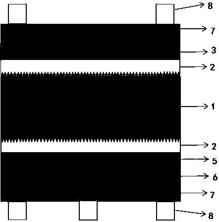
[0032] see figure 2 , the emitter structure of a double-layer amorphous silicon doped layer solar cell related to the present invention, it includes an N-type crystalline silicon wafer 1, and the front and back sides of the N-type crystalline silicon wafer 1 are provided with amorphous silicon substrates. Levy layer 2;

[0033] The outside of the amorphous silicon intrinsic layer 2 on the front is provided with an amorphous silicon doped layer N layer 3, and the outside of the front amorphous silicon doped layer N layer 3 is provided with a TCO conductive film 7, and the TCO Several Ag electrodes 8 are provided on the outside of the conductive film 7;

[0034] The outside of the amorphous silicon intrinsic layer 2 on the back is provided with a first doped layer 5, and the outside of the first doped layer 5 is provided with a second doped layer 6, and the second doped layer A TCO conductive film 7 is provided on the outside of the heterogeneous layer 6 , and several Ag elec...

Embodiment 2

[0047] see figure 2 , the emitter structure of a double-layer amorphous silicon doped layer solar cell that the present invention relates to comprises an N-type crystalline silicon chip 1, and the front and back sides of the N-type crystalline silicon chip 1 are provided with amorphous silicon substrates. Levy layer 2;

[0048] The outside of the amorphous silicon intrinsic layer 2 on the front is provided with an amorphous silicon doped layer N layer 3, and the outside of the front amorphous silicon doped layer N layer 3 is provided with a TCO conductive film 7, and the TCO Several Ag electrodes 8 are provided on the outside of the conductive film 7;

[0049] The outside of the amorphous silicon intrinsic layer 2 on the back is provided with a first doped layer 5, and the outside of the first doped layer 5 is provided with a second doped layer 6, and the second doped layer A TCO conductive film 7 is provided on the outside of the heterogeneous layer 6 , and several Ag elec...

Embodiment 3

[0062] see figure 2 , the emitter structure of a double-layer amorphous silicon doped layer solar cell related to the present invention, it includes an N-type crystalline silicon wafer 1, and the front and back sides of the N-type crystalline silicon wafer 1 are provided with amorphous silicon substrates. Levy layer 2;

[0063] The outside of the amorphous silicon intrinsic layer 2 on the front is provided with an amorphous silicon doped layer N layer 3, and the outside of the front amorphous silicon doped layer N layer 3 is provided with a TCO conductive film 7, and the TCO Several Ag electrodes 8 are provided on the outside of the conductive film 7;

[0064] The outside of the amorphous silicon intrinsic layer 2 on the back is provided with a first doped layer 5, and the outside of the first doped layer 5 is provided with a second doped layer 6, and the second doped layer A TCO conductive film 7 is provided on the outside of the heterogeneous layer 6 , and several Ag elec...


PUM


Abstract

The invention relates to an emitter structure of a double-layer amorphous silicon doped layer solar cell and a preparation method of the emitter structure. The structure comprises an N-type crystal silicon wafer, wherein amorphous silicon intrinsic layers are arranged on the front surface and the back surface of the N-type crystal silicon wafer; TCO conductive films are arranged on the outer sidesof the amorphous silicon intrinsic layers; a plurality of Ag electrodes are arranged on the outer side of the TCO conductive film; two amorphous silicon doping layers with different doping concentrations are arranged between the amorphous silicon intrinsic layer and the TCO conducting film on the back face, namely the first doping layer and the second doping layer, the first doping layer is arranged on the side close to the amorphous silicon intrinsic layer, and the second doping layer is arranged on the side close to the TCO conducting film. The amorphous silicon doped layer of the backlightsurface adopts double amorphous silicon doped layers, 0.5%-1% doping concentration is adopted in the first layer, and 1%-4% doping concentration is adopted in the second layer, so that the conductivity of the thin film is improved, the transmittance of the thin film is not reduced, and the photoelectric conversion efficiency of the HJT solar cell is improved.

Description

technical field [0001] The invention relates to the technical field of high-efficiency photovoltaic cells, in particular to an emitter structure of a double-layer amorphous silicon doped layer solar cell and a preparation method thereof. Background technique [0002] With the rapid development of photovoltaic technology, the conversion efficiency of crystalline silicon solar cells is increasing year by year. In the current photovoltaic industry, the conversion efficiency of monocrystalline silicon solar cells has reached more than 20%, and the conversion efficiency of polycrystalline silicon solar cells has reached more than 18.5%. However, the silicon-based solar cells produced on a large scale and with a conversion efficiency of more than 22.5% are only the Interdigitated Back Contact (IBC) solar cells of SunPower of the United States and the amorphous silicon / crystalline silicon with intrinsic thin layers of Panasonic of Japan. Heterojunction with Intrinsic Thin layer (H...

Claims


Application Information

Patent Timeline
Patent Type & Authority Applications(China)
IPC IPC(8): H01L31/072H01L31/0725H01L31/074H01L31/0224H01L31/18
CPCH01L31/022425H01L31/072H01L31/0725H01L31/074Y02E10/50Y02P70/50
Inventor 郭小勇易治凯汪涛王永谦
Owner SUZHOU AIKANG LOW CARBON TECH INST
Learn More