Current measurement device and current measurement method based on current divider

A technology of current measurement device and shunt, which is applied in the direction of measurement using digital measurement technology, which can solve the problems of redundant sampling signal lines and low measurement accuracy, improve anti-interference ability, improve insulation withstand voltage ability, and solve measurement errors Increased effect

Inactive Publication Date: 2019-04-16
常州是为电子有限公司
View PDF5 Cites 8 Cited by
  • Summary
  • Abstract
  • Description
  • Claims
  • Application Information

AI Technical Summary

Problems solved by technology

[0006] The technical problem to be solved by the present invention is to overcome the defects of the prior art, and provide a current measuring device based on a shunt, which not only has the advantage of digital acquisition, but also can improve its anti-interference ability, and solve the problem of long sampling signal lines in traditional methods. The introduction of electromagnetic interference leads to the disadvantage of low measurement accuracy, and the output data can be corrected in time for temperature changes, thereby reducing measurement errors and improving measurement accuracy

Method used


Image

  • Current measurement device and current measurement method based on current divider
  • Current measurement device and current measurement method based on current divider
  • Current measurement device and current measurement method based on current divider

Examples


Embodiment Construction

[0042] In order to make the content of the present invention easier to be understood clearly, the following further describes the present invention in detail based on specific embodiments in conjunction with the accompanying drawings.

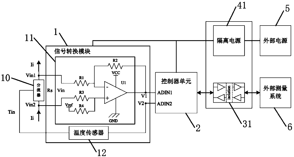
[0043] figure 1 It is a functional block diagram of a current measuring device based on a shunt according to an embodiment of the present invention.

[0044] See figure 1 As shown, a current measuring device based on a shunt includes:

[0045] The signal conversion module 1 and the controller unit 2 connected to the signal conversion module 1; wherein,

[0046] The signal conversion module 1 includes a shunt voltage acquisition circuit 11 and a temperature sensor 12;

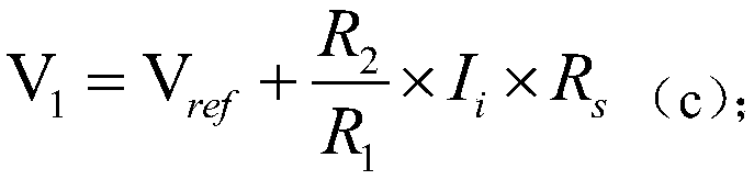
[0047] The shunt voltage collecting circuit 11 is connected to the shunt 10, and the shunt voltage collecting circuit 11 is adapted to collect the sampled current signal passing through the shunt 10, and convert the collected sampled current signal into a sampled voltage signal, and ou...


PUM


Abstract

The invention discloses a current measurement device and current measurement method based on a current divider. The current measurement device comprises a signal conversion module and a controller unit connected with the signal conversion module, wherein the signal conversion module includes a current divider voltage acquisition circuit and a temperature sensor; the current divider voltage acquisition circuit is connected with the current divider, the current divider voltage acquisition circuit is suitable for acquiring a sampling current signal passing through the current divider, convertingthe acquired sampling current signal into a sampling voltage signal and outputting the sampling voltage signal to the controller unit; the temperature sensor is suitable for being set on the current divider and outputting a sampling signal acquired by the temperature sensor to the controller unit; and the controller unit is suitable for generating an actually measured current value of the currentdivider according to the feedback sampling current signal and sampling signal. The current measurement device not only has an advantage of digital acquisition and can improve the anti-interference ability thereof, but also can timely correct the output data in allusion to the temperature change, thereby reducing the measurement error, and improving the measurement accuracy.

Description

Technical field [0001] The invention relates to a current measuring device and a current measuring method based on a shunt. Background technique [0002] At present, with the increasing use of new energy vehicles and battery energy storage systems as its main power source, how to more accurately monitor changes in various indicators during battery operation has become the main direction of new energy technology development; Many key indicators such as the state of charge parameter SOC, the maximum output power SOP and the battery life SOH in the energy storage system all use current measurement as its calculation input. Therefore, it is very important to improve the measurement accuracy of the battery energy storage system working current. significance. [0003] The Hall element is usually used as the front-end sensor for current measurement in battery energy storage systems. Although it has good electrical isolation characteristics and a wide measurement range, the Hall sensor ha...

Claims


Application Information

Patent Timeline
Patent Type & Authority Applications(China)
IPC IPC(8): G01R19/25
CPCG01R19/25
Inventor 阳威杨锡旺
Owner 常州是为电子有限公司
Why Eureka
Try Eureka