
Device and method for measuring optical parameter field of diffuse medium based on time-frequency optical information fusion

A technique of dispersive media and optical parameters, applied in the field of optical imaging, can solve the problems of low reconstruction accuracy of optical parameter fields and less measurement data, and achieve the effect of solving reconstruction problems and accurate reconstruction problems

Active Publication Date: 2021-05-04
HARBIN INST OF TECH
View PDF5 Cites 0 Cited by
  • Summary
  • Abstract
  • Description
  • Claims
  • Application Information

AI Technical Summary

Problems solved by technology

[0006] The purpose of the present invention is to solve the problem of less measurement data obtained and low precision of optical parameter field reconstruction by using a single model measurement signal in the existing simultaneous reconstruction process of the distribution of the absorption and scattering coefficients of the diffuse medium, and proposes a Device and method for measuring optical parameter field of diffuse medium based on time-frequency optical information fusion

Method used


Image

  • Device and method for measuring optical parameter field of diffuse medium based on time-frequency optical information fusion
  • Device and method for measuring optical parameter field of diffuse medium based on time-frequency optical information fusion
  • Device and method for measuring optical parameter field of diffuse medium based on time-frequency optical information fusion

Examples


specific Embodiment approach 1

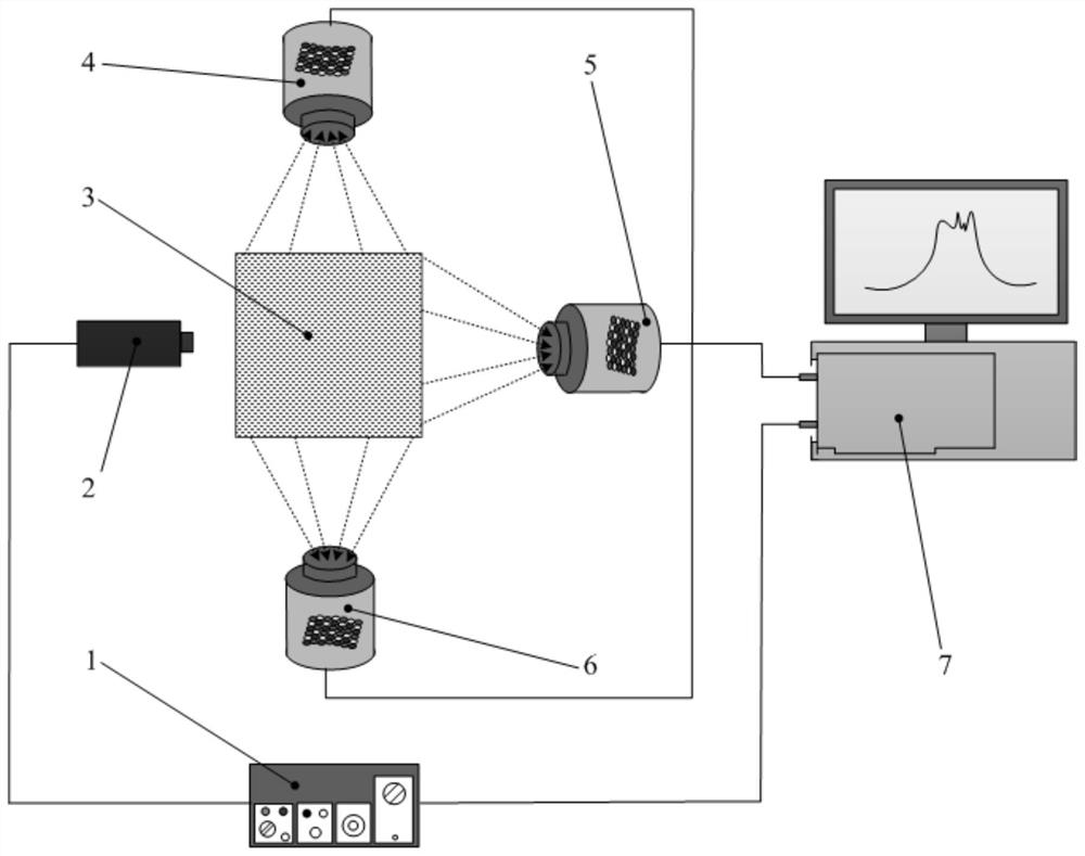
[0040] The device for measuring the optical parameter field of a diffuse medium based on time-frequency optical information fusion in this embodiment, such as figure 1As shown, the measuring device includes a laser controller 1, a laser head 2, a dispersive medium 3, a group of microlens array light field cameras 4 and a data acquisition and processing system 7;

[0041] One end of the laser controller 1 is connected to the laser control signal output end of the laser head 2, and the other end of the laser controller 1 is connected to the data acquisition and processing system 7; The signal output terminal is connected; wherein, all the microlens array light field cameras 4 are on the same plane as the laser head 2, and the laser head 2 and a group of microlens array light field cameras 4 are evenly distributed around the dispersive medium 3;

[0042] Moreover, when the laser light emitted by the laser head 2 enters the dispersive medium 3 , the laser light emitted by the lase...

specific Embodiment approach 2

[0044] The difference from Embodiment 1 is that, in the device for measuring the optical parameter field of a diffuse medium based on time-frequency optical information fusion in this embodiment, the number of the microlens array light field cameras 4 is the same as the shape of the diffuse medium 3. Adaptation, when the shape of the dispersion medium 3 is cylindrical, the number of microlens array light field cameras 4 is 2, which are respectively arranged on the boundary surface side formed by the two ends of the dispersion medium 3; when the shape of the dispersion medium 3 is In the case of a regular prism, the number of microlens array light field cameras 4 is the number of boundary surfaces of the diffuse medium 3 minus 1.

specific Embodiment approach 3

[0046] Different from the second specific embodiment, the device for measuring the optical parameter field of a diffuse medium based on time-frequency optical information fusion in this embodiment, such as figure 1 As shown, when the shape of the dispersion medium 3 is a square, the number of microlens array light field cameras 4 is three, including the first microlens array light field camera 4, the second microlens array light field camera 5 and the second microlens array light field camera 5. Three microlens array light field cameras 6, one end of the laser controller 1 is connected to the laser control signal output end of the laser head 2, and the other end of the laser controller 1 is connected to the data acquisition and processing system 7; the signal input end of the data acquisition and processing system 7 is simultaneously Connect with the signal output end of the first microlens array light field camera 4, the second microlens array light field camera 5, and the thi...


PUM


Abstract

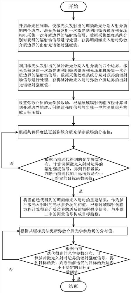
A device and method for measuring the optical parameter field of a diffuse medium based on time-frequency optical information fusion. The invention belongs to the technical field of optical imaging. In the existing simultaneous reconstruction process of the distribution of the absorption and scattering coefficients of the diffuse medium, the reconstruction using the measurement signal of a single model has the problems of less measurement data and low reconstruction accuracy of the optical parameter field. The invention includes: using a light field camera with a microlens array to respectively obtain radiation intensity information in various directions of the boundary of the diffuse medium under the action of frequency-modulated laser and pulsed laser, and by simulating the transmission process of infrared radiation in the dispersed medium under the action of frequency-modulated laser, the preliminary obtained The reconstructed image of the optical parameter field inside the medium under the frequency domain model is used as the initial optical parameter field of the time domain model. By simulating the infrared radiation transmission process in the dispersed medium under the action of pulsed laser, the internal structure of the dispersed medium is obtained. Using the method of the invention can complete the reconstruction of high-precision optical parameter field.

Description

technical field [0001] The invention relates to an optical imaging method, in particular to a measuring device and method for the optical parameter field of a diffuse medium. Background technique [0002] Dispersed medium is a participating medium containing particles. The optical parameter field distribution inside the dispersed medium is often not directly obtained by measurement, but it can be reconstructed by optical parameter field, using the optical information in the measurement signal of the medium boundary, combined with the reconstruction optimization algorithm, The optical parameter field inside the medium is obtained, so as to detect the internal structure of the dispersed medium. Optical parameter reconstruction of diffuse media plays an important role in many fields of research, such as biomedical imaging, non-destructive detection, infrared remote sensing, flame temperature measurement and other fields. [0003] When the laser is incident on the dispersive me...

Claims


Application Information

Patent Timeline
Patent Type & Authority Patents(China)
IPC IPC(8): G01N21/47G01N21/59
CPCG01N21/47G01N21/59G01N2021/4735
Inventor 齐宏赵方舟任亚涛阮立明赵春晖
Owner HARBIN INST OF TECH
Learn More