
Laser emission gun with recoil force

A technology of laser emission and recoil, applied in the field of simulation training, can solve problems such as unfavorable use, inability to reflect the shooting experience, inconsistent use environment, etc.

Pending Publication Date: 2019-04-16
11TH RES INST OF CHINA ELECTRONICS TECH GROUP CORP
View PDF0 Cites 8 Cited by
  • Summary
  • Abstract
  • Description
  • Claims
  • Application Information

AI Technical Summary

Problems solved by technology

This technical solution has the following technical problems: 1) When using blank bullets, the user feels real and has strong recoil, but it is necessary to install a blank bullet retreater to realize the continuous firing function, and the installation process is relatively cumbersome; 2 ) Although the blank bomb has no warhead, the high-temperature and high-pressure gas produced by itself is quite dangerous, and the safety is low. When the bomb is loaded, when the trigger is only used to mechanically trigger the laser, there is no recoil, which does not match the actual use environment and cannot reflect the real shooting experience.

Method used


Image

  • Laser emission gun with recoil force
  • Laser emission gun with recoil force
  • Laser emission gun with recoil force

Examples


Embodiment Construction

[0024] Exemplary embodiments of the present disclosure will be described in more detail below with reference to the accompanying drawings. While exemplary embodiments of the present disclosure are shown in the drawings, it should be understood that the present disclosure may be embodied in various forms and should not be limited by the embodiments set forth herein. Rather, these embodiments are provided so that the present disclosure will be more thoroughly understood, and will fully convey the scope of the present disclosure to those skilled in the art.

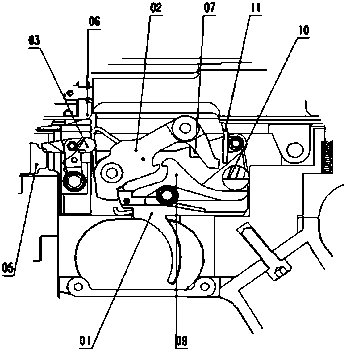
[0025] The first embodiment of the present invention provides a laser emitting gun with recoil, such as figure 1 shown is an example diagram of the overall structure of the laser gun; such as figure 2 Shown is a schematic diagram of the local structure of the laser launch gun; it specifically includes: trigger 01, impact swing arm 02, air valve swing arm 03, air cylinder 04, air valve 05, gun bolt 06, light-emitting diode ...


PUM


Abstract

The invention introduces a laser emission gun with a recoil force. The laser emission gun comprises a trigger, an impact swing arm, an air valve opening swing arm, an air cylinder, an air valve, a bolt, a light emitting diode, an infrared receiver, a laser emitter and a reset spring. Under the state that the trigger is pulled, the trigger rotates anticlockwise until a front-end stop block portionof the trigger does not block a front-end stop block portion of the impact swing arm any longer so that the impact swing arm can rotate anticlockwise and can strike the air valve opening swing arm, anair valve of the air cylinder is opened under striking of the air valve opening swing arm, so that high-pressure gas in the air cylinder flows into the bolt, the bolt moves in the direction towards agun tail under the action of the high-pressure gas so as to generate the recoil force, in addition, when the impact swing arm rotates anticlockwise, a light beam emitted by the light emitting diode is not blocked by the impact swing arm, so that the infrared receiver sends an emitting instruction to the laser emitter when receiving the light beam.

Description

technical field [0001] The invention relates to the technical field of simulation training, in particular to a laser emitting gun with recoil. Background technique [0002] In the current simulated confrontation training, the laser launcher used is an integrated type, that is, the laser launcher is installed on the real gun, and the laser is triggered mechanically by the trigger or by collecting the sound of blank bullets. This technical solution has the following technical problems: 1) When using blank ammunition, the user feels real and has strong recoil, but it is necessary to install blank ammunition ejector to realize the burst function, and the installation process is cumbersome; 2 ) Although the empty bomb has no warhead, the high-temperature and high-pressure gas generated by itself is quite dangerous and has low safety. It can only be used by troops that have undergone strict formal training, which is not conducive to the use of other occasions; 3) When the empty bo...

Claims


Application Information

Patent Timeline
Patent Type & Authority Applications(China)
IPC IPC(8): F41A33/02F41A33/06
CPCF41A33/02F41A33/06
Inventor 李长桢廖向农
Owner 11TH RES INST OF CHINA ELECTRONICS TECH GROUP CORP
Learn More