
Wire surface treatment process

A surface treatment and surface treatment device technology, which is applied in the direction of manufacturing tools, metal processing equipment, and machine tools designed for grinding the rotating surface of workpieces, etc., can solve the problems of low surface treatment efficiency and poor surface treatment effect of wire rods, and achieve improvement Surface treatment efficiency, the effect of enhancing the rotation effect

Active Publication Date: 2019-04-16
佛山市开源林辉五金实业有限公司
View PDF6 Cites 4 Cited by
  • Summary
  • Abstract
  • Description
  • Claims
  • Application Information

AI Technical Summary

Problems solved by technology

During the production process of the wire rod, the surface treatment of the wire rod is required, so that the wire rod has a good surface quality and is convenient for the subsequent use of the wire rod. However, the existing wire rod surface treatment process has a low surface treatment efficiency for the wire rod. The surface treatment effect of the wire rod is not good, and it cannot meet the increasingly high quality requirements of the current society. Therefore, a new wire surface treatment process is urgently needed to treat the wire rod.

Method used


Image

  • Wire surface treatment process
  • Wire surface treatment process
  • Wire surface treatment process

Examples

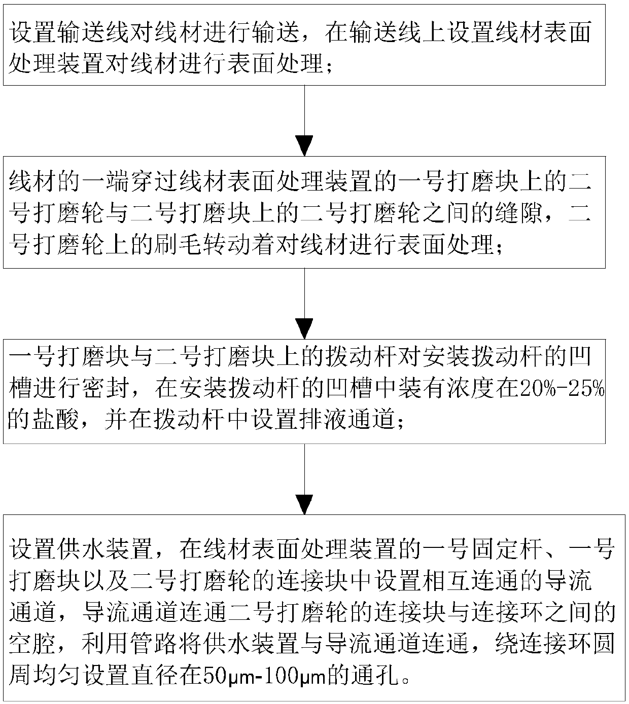

Embodiment Construction

[0025] In order to make the technical means, creative features, goals and effects achieved by the present invention easy to understand, the present invention will be further described below in conjunction with specific embodiments.

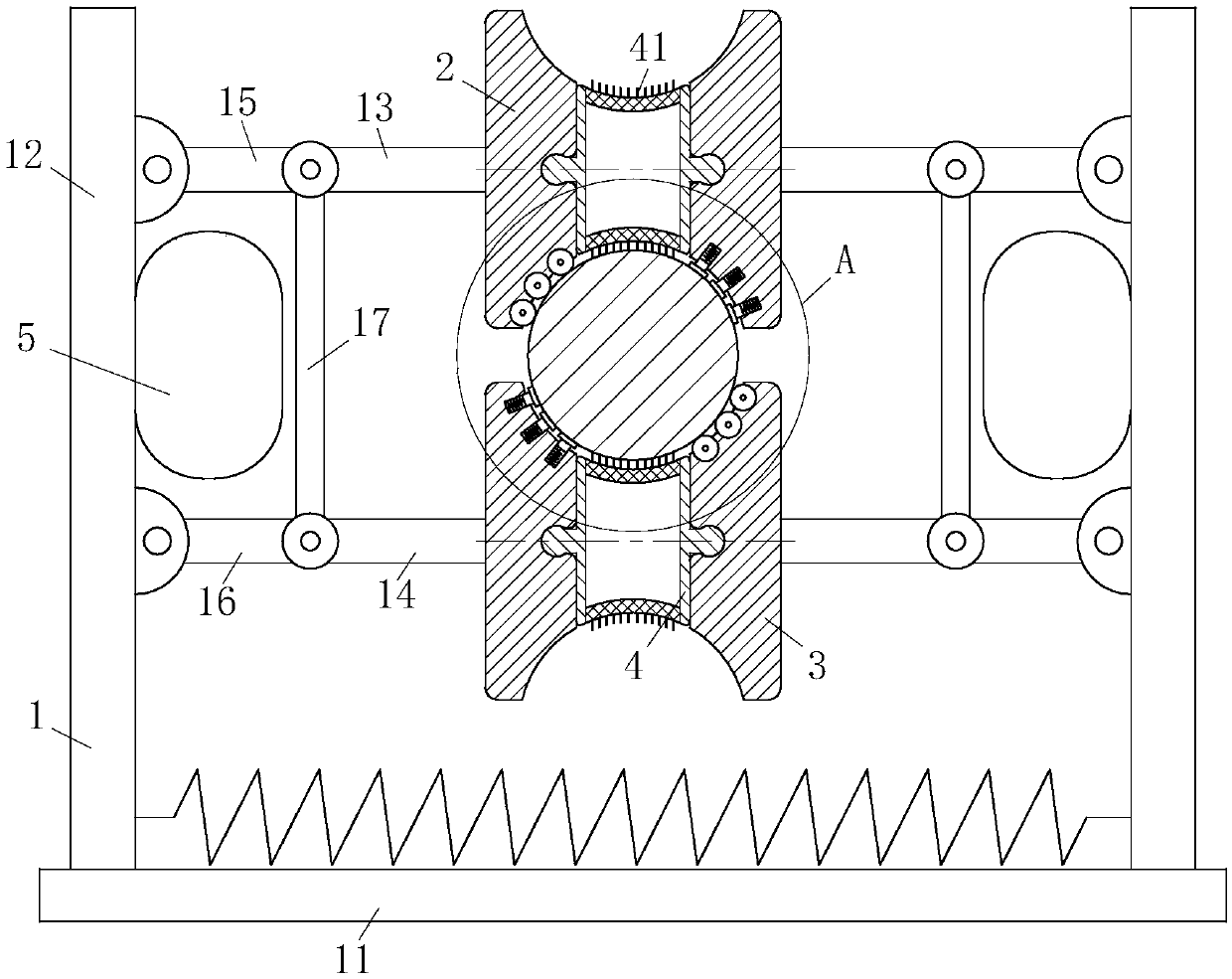
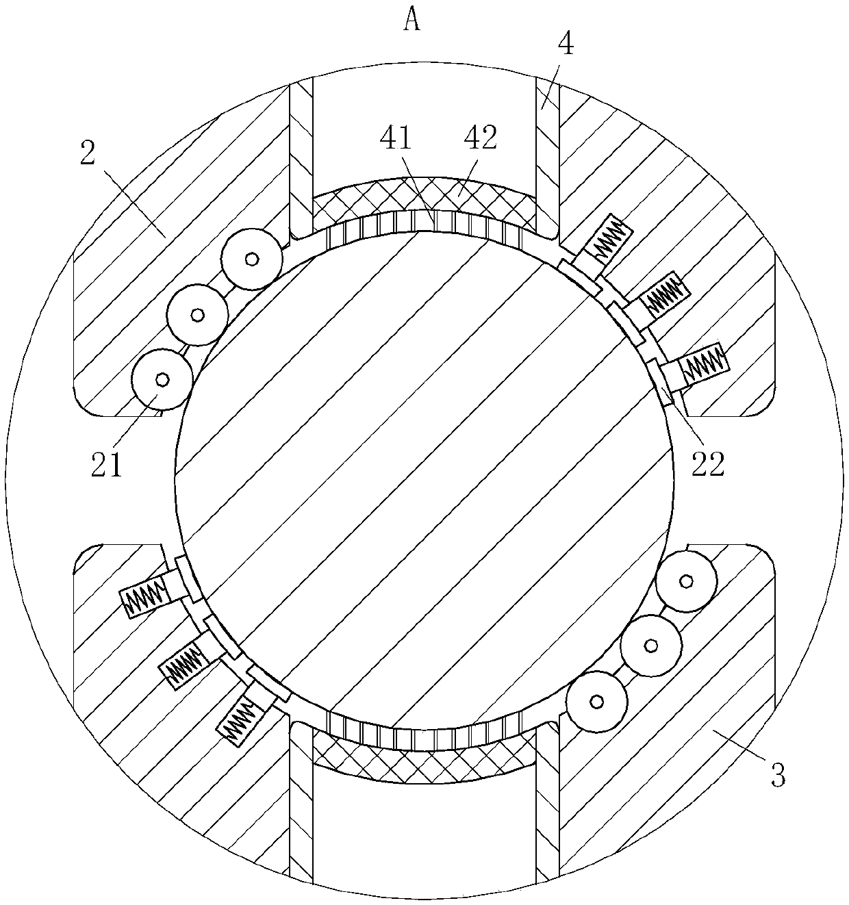
[0026] Such as Figure 1 to Figure 6 Shown, a kind of wire rod surface treatment process of the present invention, this process comprises the steps:

[0027] S1: Set up a conveying line to convey the wire, and set a wire surface treatment device on the conveying line to perform surface treatment on the wire;

[0028] S2: One end of the wire passes through the gap between the No. 2 grinding wheel on the No. 1 grinding block of the wire surface treatment device in S1 and the No. 2 grinding wheel on the No. 2 grinding block, and the bristles on the No. 2 grinding wheel rotate Surface treatment of the wire; the friction between the movement of the wire and the bristles makes the No. 2 grinding wheel and the bristles rotate to perform surface treatment ...


PUM


Abstract

The invention belongs to the technical field of wire surface treatment, and particularly relates to a wire surface treatment process. The wire surface treatment process comprises the following steps that a transporting line is arranged to transport the wire, and a wire surface treatment device is arranged on the conveying line to carry on the surface treatment on the wire; one end of the wire penetrates through the gap between a second polishing wheel on a first polishing block and a second polishing wheel on a second polishing block on the wire surface treatment device; poking rods on the first polishing block and the second polishing block seal grooves for mounting the poking rods, the grooves are loaded with hydrochloric acid with the concentration being 20-25%, and a liquid dischargingchannel is arranged in each poking rod; and a water supply device is arranged, flow diversion channels communicating with one another are arranged in a first fixed rod, the first polishing block of the wire surface treatment device and a connecting block of the second polishing wheel, the flow diversion channels communicate with a cavity between the connecting block and a connecting ring of the second polishing wheel, the water supply device communicates with the flow diversion channels through a pipeline, and through holes with the diameter of 50-100 [mu]m are evenly formed in the peripheryof the connecting ring.

Description

technical field [0001] The invention belongs to the technical field of wire surface treatment, in particular to a wire surface treatment process. Background technique [0002] Wire rod is the smallest section size of hot-rolled section steel. In my country, the hot-rolled round steel supplied in coils with a diameter of 5-9 mm and a total of eight specifications is called wire rod. Wire rod is also called wire rod because it is delivered in coils. During the production process of the wire rod, the surface treatment of the wire rod is required, so that the wire rod has a good surface quality and is convenient for the subsequent use of the wire rod. However, the existing wire rod surface treatment process has a low surface treatment efficiency for the wire rod. The surface treatment effect of the wire rod is not good, and it cannot meet the increasingly high quality requirements of the current society. Therefore, a new wire surface treatment process is urgently needed to tre...

Claims


Application Information

Patent Timeline
IPC IPC(8): B24B5/38B24B27/00B24B27/033B24B41/00B24B47/12B24B55/02B24B55/06C23G3/02
CPCB24B5/38B24B27/0015B24B27/0076B24B27/033B24B41/00B24B47/12B24B55/02B24B55/06C23G3/027
Inventor 邱宇豪郭义强胡子航
Owner 佛山市开源林辉五金实业有限公司
Learn More