
Load unloading method and load unloading device of power system

A technology of power system and load information, applied in the field of electric power, can solve the problems of weak generalization ability of arc fault identification, complicated calculation, and no consideration of operation constraints.

Inactive Publication Date: 2019-04-12
GUANGDONG UNIV OF PETROCHEMICAL TECH
View PDF6 Cites 0 Cited by
  • Summary
  • Abstract
  • Description
  • Claims
  • Application Information

AI Technical Summary

Problems solved by technology

However, this control method has the following problems: 1) Renewable energy generation and load forecast data are required, and the accuracy of the forecast data has a great impact on the effectiveness of the control strategy; 2) The network topology information, various The unified processing of a large amount of data such as node state quantities and reactive power / voltage adjustment equipment parameters leads to complex calculations, long calculation time, and it is difficult to meet the real-time requirements of the active power distribution network; 3) There is a convergence problem in the optimization calculation method
[0006] The optimization model in the existing power system load method is relatively simple, and does not consider the operational constraints in actual operation, which makes the above-mentioned regulation method less adaptable in the actual regulation of isolated power systems; at the same time, the generalization ability of arc fault identification at the load end of the power system Not strong, failed to propose a detection scheme applicable to different types of loads, which can prevent the misjudgment of arc fault detection caused by the rated current of nonlinear loads and the starting current of frequent switching inductive loads

Method used

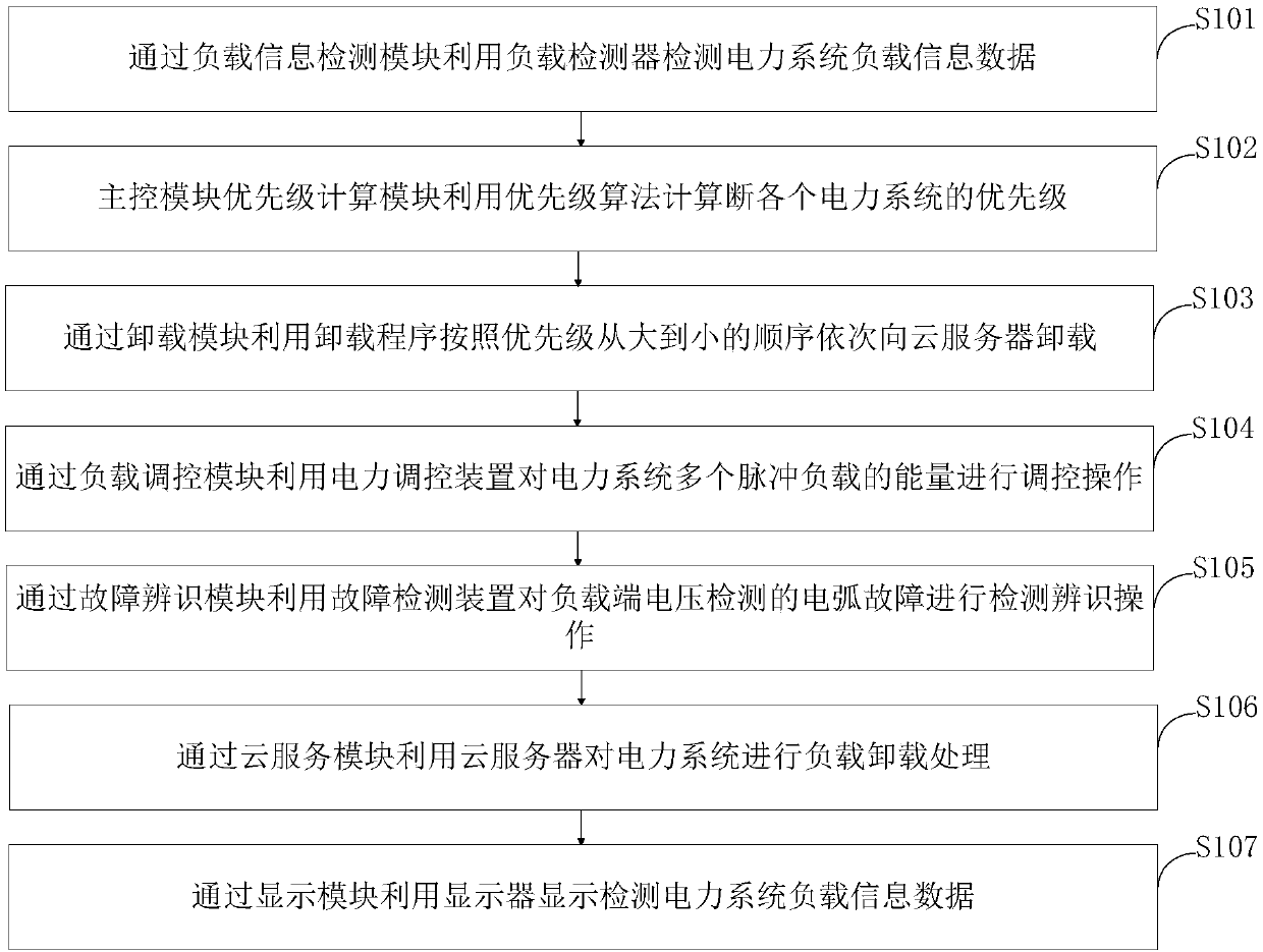
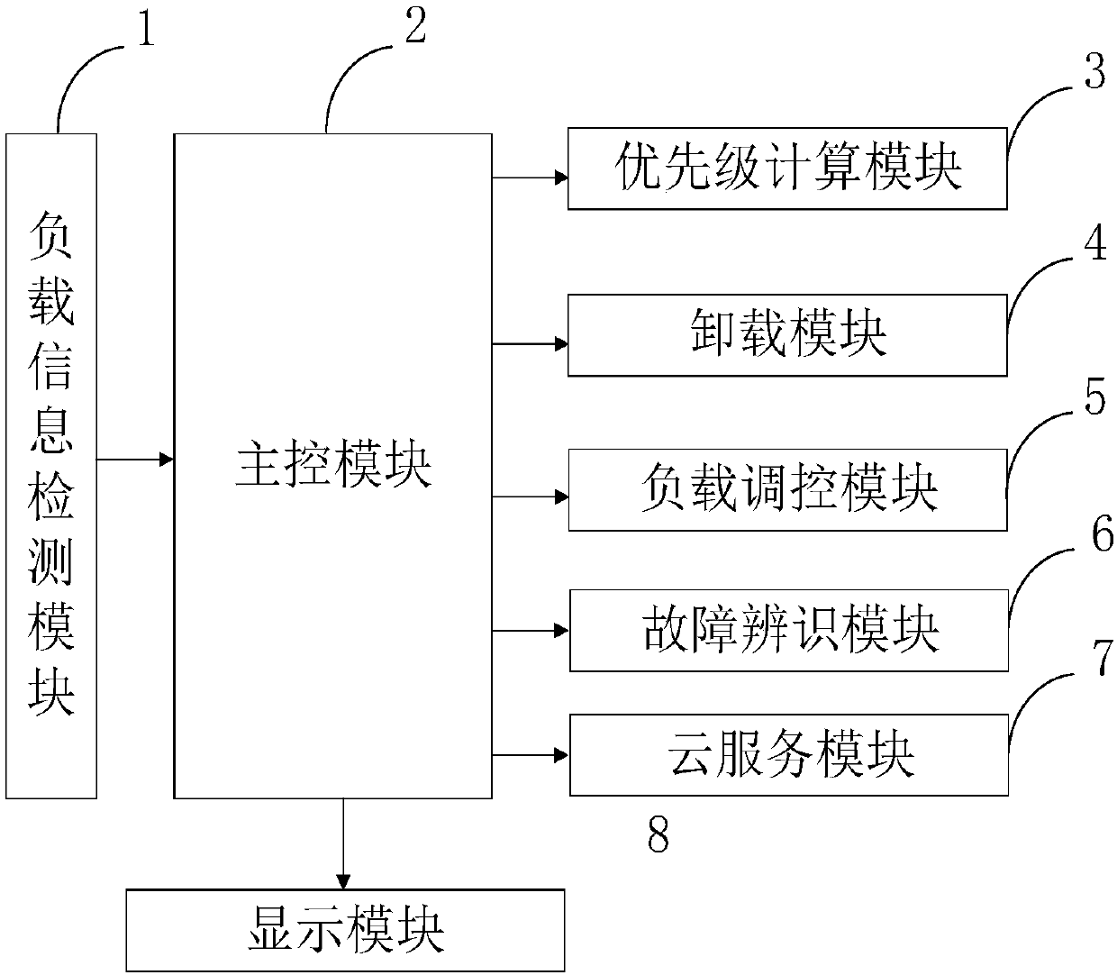

Image

  • Load unloading method and load unloading device of power system
  • Load unloading method and load unloading device of power system
  • Load unloading method and load unloading device of power system

Examples


Embodiment Construction

[0067] In order to further understand the content, features and effects of the present invention, the following examples are given, and detailed descriptions are given below with reference to the accompanying drawings.

[0068] The optimization model in the existing power system load method is relatively simple, and does not consider the operational constraints in actual operation, which makes the above-mentioned regulation method less adaptable in the actual regulation of isolated power systems; at the same time, the generalization ability of arc fault identification at the load end of the power system It is not strong, and a detection scheme applicable to different types of loads cannot be proposed, which can prevent the misjudgment of arc fault detection caused by the rated current of nonlinear loads and the starting current of frequent switching inductive loads.

[0069] In order to solve the above technical problems, the structure of the present invention will be described...


PUM


Abstract

The invention belongs to the technical field of power, and discloses a load unloading method and load unloading device of a power system. The load unloading device of the power system comprises a loadinformation detection module, a master control module, a priority calculation module, an unloading module, a load control module, a fault identification module, a cloud service module and a display module. By the load control module, energy of a pulse load in an independent power system can be controlled very well; and meanwhile, the load at each branch end in a power distribution line is monitored by the fault identification module, analogue / digital conversion is performed on a sampling signal, a load digital signal output from the monitoring unit is transmitted to the fault identification unit, the load digital signal is decomposed through wavelet transform by a microprocessor MCU, and the arc fault identification capability of the load end is greatly improved.

Description

technical field [0001] The invention belongs to the technical field of electric power, and in particular relates to a load unloading method and a load unloading device of an electric power system. Background technique [0002] The power system is an electric energy production and consumption system composed of power plants, power transmission and transformation lines, power supply and distribution stations, and power consumption. Its function is to convert the primary energy in nature into electric energy through the power generation device, and then supply the electric energy to various users through power transmission, transformation and distribution. In order to realize this function, the power system also has corresponding information and control systems in various links and different levels to measure, adjust, control, protect, communicate and dispatch the production process of electric energy, so as to ensure that users obtain safe and high-quality electric energy. . ...

Claims


Application Information

Patent Timeline
IPC IPC(8): H02J3/14
CPCH02J3/14H02J2203/20Y04S20/222Y02B70/3225
Inventor 马远佳翟明岳崔得龙方波彭志平
Owner GUANGDONG UNIV OF PETROCHEMICAL TECH
Learn More