
An anti-condensation ventilation device for a ring network cabinet

A ventilation device and anti-condensation technology, applied in the substation/distribution device enclosure, substation/switchgear cooling/ventilation, substation/switch layout details, etc. and other problems to achieve the effect of reducing potential safety hazards, improving power supply reliability, and reducing temperature

Active Publication Date: 2020-09-01
STATE GRID SHANDONG ELECTRIC POWER +1
View PDF6 Cites 0 Cited by
  • Summary
  • Abstract
  • Description
  • Claims
  • Application Information

AI Technical Summary

Problems solved by technology

[0005] The present invention aims at the above-mentioned deficiencies existing in the prior art, and provides an anti-condensation ventilation device for the ring main unit. Hot air can only flow out of the cable trench from the sealing ring, causing the hot air in the cable trench to enter the cabinet, so as to realize timely ventilation inside the cable trench, reduce the temperature in the cable trench, and avoid hot air in the cable trench It enters the cabinet to form condensation phenomenon, thereby avoiding the corrosion of automatic mechanisms such as circuit breakers and load switches in the cabinet, which leads to the problem that the switch cannot operate correctly, improves the reliability of power supply, and does not need to spend a lot of manpower and material resources on the ring network cabinet. The erasure of dew reduces the potential safety hazard

Method used


Image

  • An anti-condensation ventilation device for a ring network cabinet
  • An anti-condensation ventilation device for a ring network cabinet
  • An anti-condensation ventilation device for a ring network cabinet

Examples


Embodiment 1

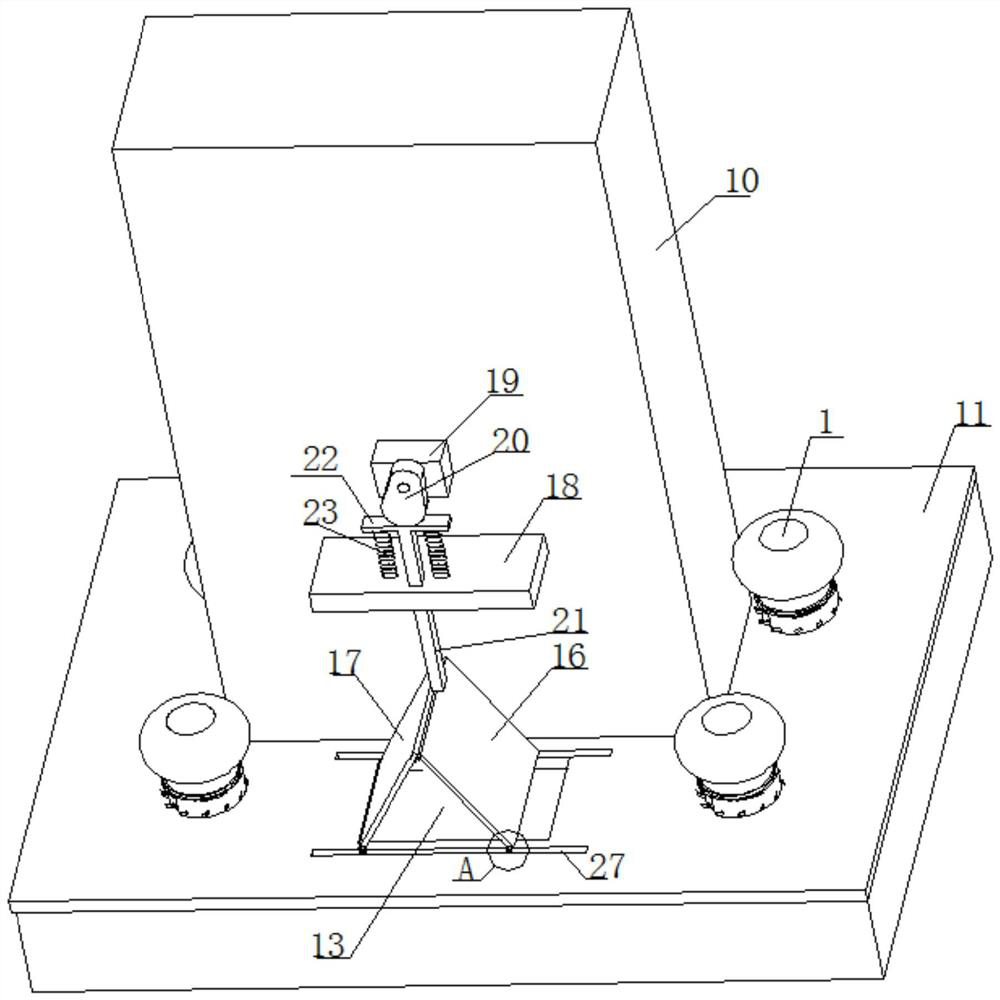
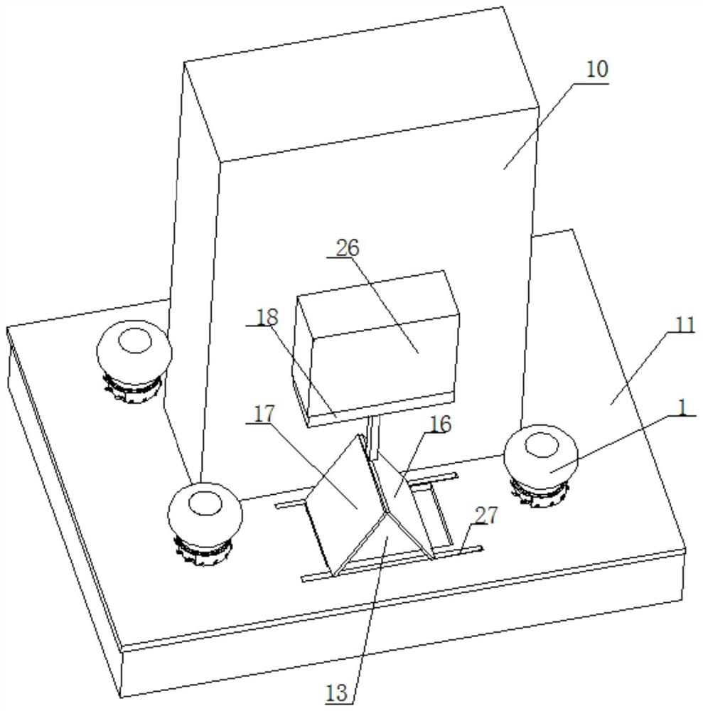
[0035] An anti-condensation ventilation device for a ring network cabinet, such as Figure 1-3 As shown, it includes a support base 11 located above the cable trench and a cabinet body 10 located above the support base 11. The cabinet body 10 and the support base 11 are connected by bolts. The support base 11 includes an upper plate and four side plates, four The side plates are all arranged under the upper plate, and the four side plates and the upper plate surround to form a shell structure with an open lower end surface.

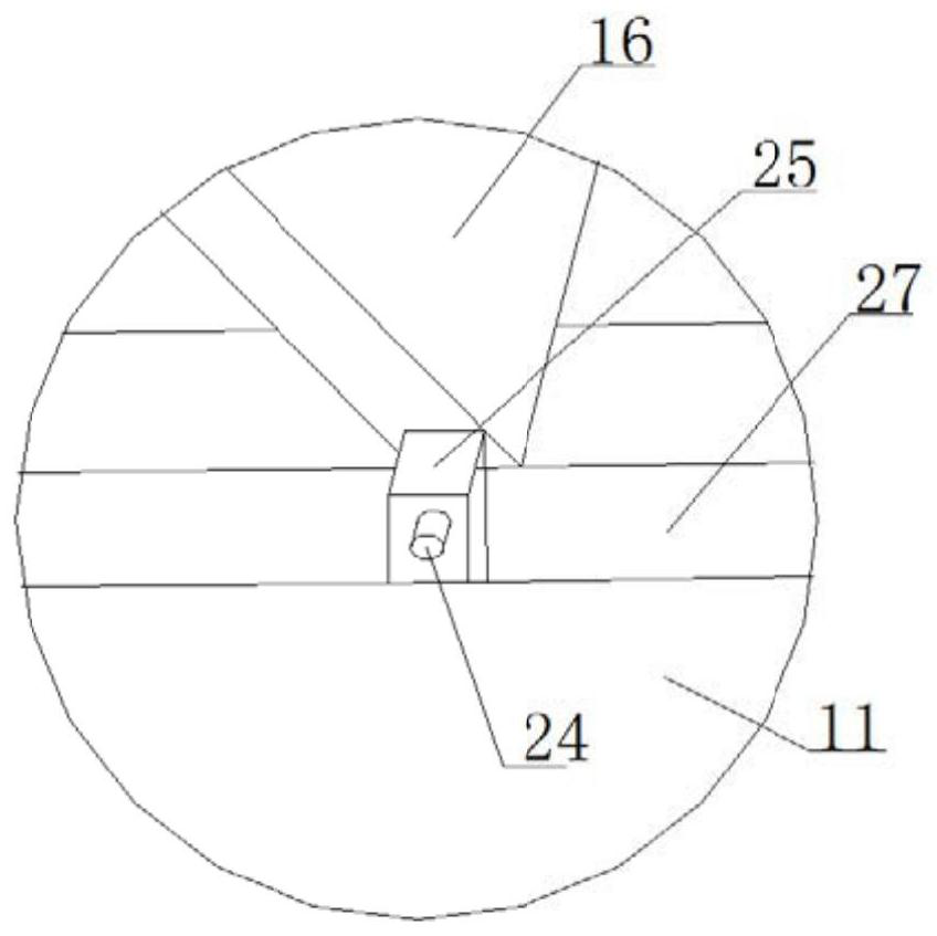
[0036] The upper plate of the support seat 11 is provided with a wind exchange window 13 and a threading hole, and the air exchange window 13 is provided with a first cover plate 16 and a second cover plate 17, one end of the first cover plate 16 and one end of the second cover plate 17 Hinged, the end of the first cover plate 16 away from the second cover plate 17 and the end of the second cover plate 17 away from the first cover plate 16 are both slidin...

Embodiment 2

[0044] This embodiment 2 is the same as embodiment 1, the difference is that, as Figure 4-6 As shown, the upper end surface of the support base 11 is provided with four auxiliary ventilation devices, and the four auxiliary ventilation devices are respectively arranged at the corners of the cabinet body 10, and the upper end surface of the support base 11 is provided with four through holes;

[0045] The auxiliary ventilation device includes a wind cap 1, a connecting pipe 2 and a support tube 8; specifically: the wind cap 1 adopts a non-powered wind cap; Both the upper end surface and the lower end surface of the support cylinder 8 are provided with connection holes, the connection pipe 2 fits with the connection hole, the connection pipe 2 can rotate in the connection hole, and the support ring 9 is arranged above the support cylinder 8, and the support ring 9 is sleeved on the The upper part of the connecting pipe 2, the supporting ring 9 is welded and fixed with the connec...

Embodiment 3

[0050] The present embodiment 3 is the same as the embodiment 2, the difference is that the anti-condensation ventilation device of the ring network cabinet of the present embodiment 3 also includes a control system, the control system includes a controller, a humidity sensor and a display, and the humidity sensor is located at In the cable trench, the humidity sensor is electrically connected to the controller, the display is electrically connected to the controller, and the controller is electrically connected to the motor 19 . When the humidity sensor monitors that the humidity in the cable trench is greater than 50%, the controller starts the motor 19 to make the ventilation device start to run, and ventilates the cable trench until the humidity in the cable trench is less than 50%.


PUM


Abstract

The invention discloses an anti-condensation ventilation device for a ring main unit, and relates to the technical field of the ventilation devices for the ring main units. The device comprises a supporting seat and a ring main unit body, wherein a first cover plate and a second cover plate are arranged in a ventilation window of an upper plate of the supporting seat; a supporting plate is arranged on one side of the ring main unit body; the ventilation device is arranged above the supporting plate; the ventilation device comprises a motor, a cam, a movable rod, a contact plate and a compression spring; a motor output shaft is connected to the cam; the movable rod is arranged below the cam; the contact plate is arranged between the movable rod and a rotary plate; the contact plate is connected to the upper end of the movable rod; the lower end of the movable rod is hinged to one end, close to the second cover plate, of the first cover plate; and the compression spring is arranged between the contact plate and the supporting plate. According to the anti-condensation ventilation device, hot air in a cable trench can be prevented from entering the ring main unit body to form a condensation phenomenon, a problem that a switch cannot act correctly due to rusting of a circuit breaker and a load switch in the ring main unit body is avoided, the power supply reliability is improved, alarge amount of manpower and material resources do not need to be consumed for erasing condensation of the ring main unit, and potential safety hazards are reduced.

Description

technical field [0001] The invention relates to the technical field of ventilation devices for ring network cabinets, in particular to an anti-condensation ventilation device for ring network cabinets. Background technique [0002] The ring network cabinet, that is, the ring network power supply unit RMU, is an emerging and rapidly developing smart grid power distribution equipment in recent years; the ring network cabinet includes a support seat above the cable trench and a cabinet above the support seat , the cabinet body is connected with the support base, the cable is coiled in the cable trench, and enters the ring network cabinet through the support base. [0003] When used in winter, the temperature difference between day and night is large. Since the cable trench is in a sealed space, the air in the cable trench is higher than the air in the ring network cabinet and the outside air. The hot air in the cable trench cannot circulate. It can enter the cabinet of the rin...

Claims


Application Information

Patent Timeline
Patent Type & Authority Patents(China)
IPC IPC(8): H02B1/56H02B1/28
CPCH02B1/28H02B1/565
Inventor 李海舰王琦刘顺华翟滢薛忠洲马涛郝洪民孙乾荆树海岳慧耿波于萌张鑫陈志敏张纪杰程晓云冯忠奎李业顺马力远
Owner STATE GRID SHANDONG ELECTRIC POWER
Learn More