
Turning over method of cutter head of super large diameter shield machine

A technology of super-large diameter, shield machine, applied in the direction of transportation and packaging, load hanging components, etc., can solve problems such as difficulty in turning over, and achieve the effect of reducing workload, reducing construction costs, and speeding up construction progress

Active Publication Date: 2020-07-31
CHINA RAILWAY TUNNEL GROUP CO LTD +1
View PDF3 Cites 0 Cited by
  • Summary
  • Abstract
  • Description
  • Claims
  • Application Information

AI Technical Summary

Problems solved by technology

[0005] The present invention aims to provide a method for turning over the cutterhead of a super-large-diameter shield machine to solve the technical problem in the prior art that it is difficult to turn over from a horizontal state to a vertical state when the cutterhead of a super-large-diameter shield machine is installed.

Method used


Image

  • Turning over method of cutter head of super large diameter shield machine
  • Turning over method of cutter head of super large diameter shield machine
  • Turning over method of cutter head of super large diameter shield machine

Examples


Embodiment 1

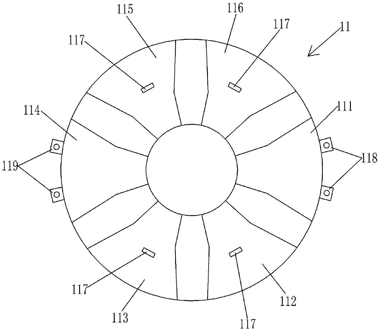
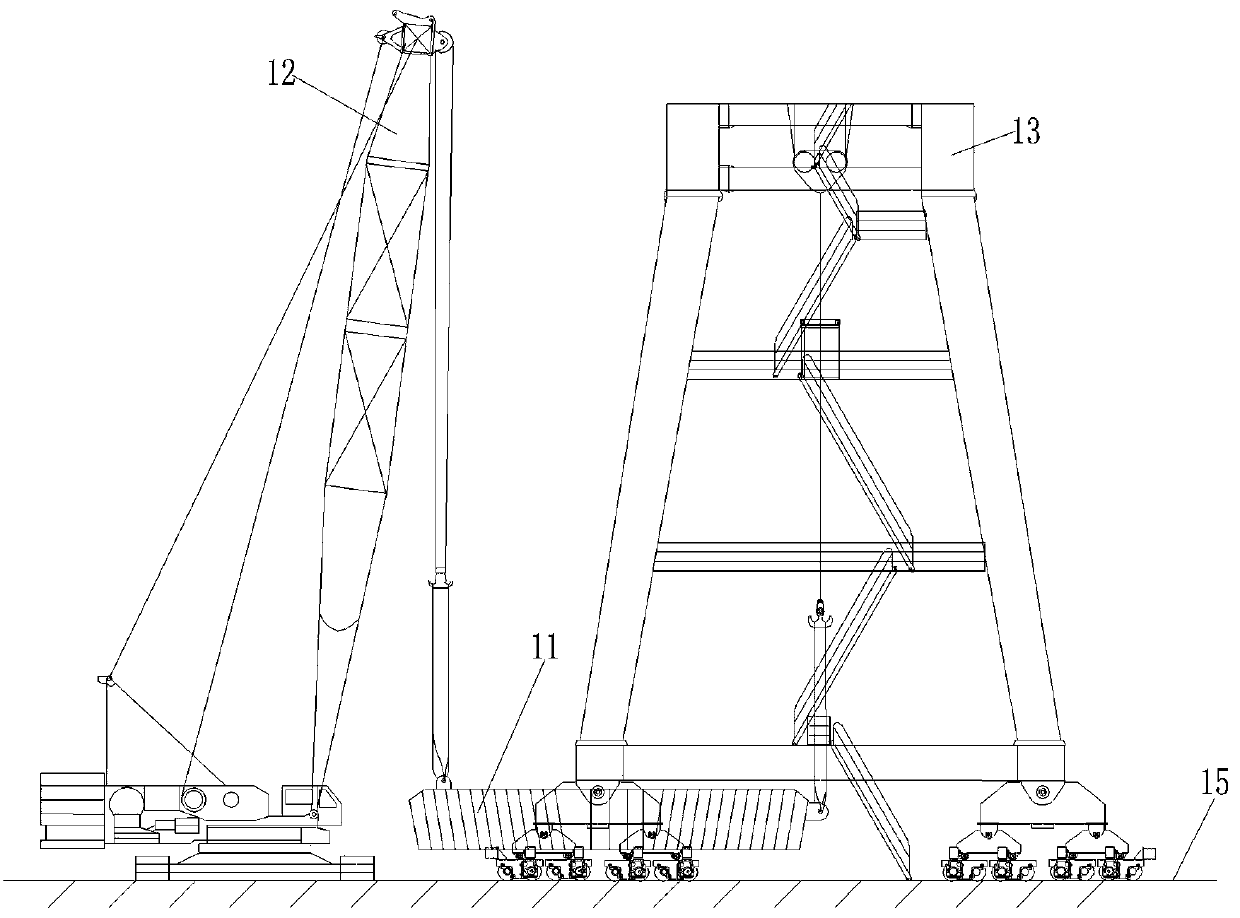
[0042] Please also refer to Figure 1 to Figure 6 .

[0043] The method for turning over the cutter head of the ultra-large diameter shield machine provided by the embodiment of the present invention is used for figure 1 The shown shield machine cutter head 11 is turning over. The shield machine cutter head 11 weighs more than 500 tons and consists of 1 central block, 6 main blocks, and 6 auxiliary blocks. It is the single block in the shield machine assembly process. The second lifter has the largest diameter and the heaviest weight. Due to the large size and weight of the cutterhead 11, the cutterhead 11 is inconvenient to transport as a whole. Therefore, one central block, six main blocks, and six auxiliary blocks of the cutterhead 11 are directly placed in the foundation pit for assembling the shield machine. Tailor welding is completed at the nearby welding assembly site, and then transferred to the vicinity of the foundation pit to avoid long-distance transportation. ...

Embodiment 2

[0064] see Figure 7 to Figure 9 .

[0065] The method for turning over the cutter head of the super-large-diameter shield machine provided by the embodiment of the present invention is used in the construction occasion of double tunnels side by side. For the corresponding working track of the gantry crane, a traversing track is laid between the two sets of working tracks, so that the gantry crane can walk from one set of working tracks to the other set of working tracks through the traversing track, so as to be used for the installation in the two tunnels. The cutter head of the shield machine is hoisted and turned over separately.

[0066] Specifically, such as Figure 7 As shown, the left working track 161 is laid on the construction site where the tunnel on the left is located, and the left operating track 161 passes through the left welding assembly site 162 for assembling the cutter head and the assembly site 162 for assembling shields on the construction site where th...


PUM


Abstract

The invention discloses an overturning method of a cutter head of a super large-diameter shield machine. A mobile crane, a gantry crane arranged on a foundation pit construction site in a manner of erection, a plurality of annular steel wire ropes and a plurality of shackles are employed by the method, and the method comprises the following steps of firstly moving the gantry crane and the crane tothe ground beside foundation pits, and making the cutter head located between the crane and the gantry crane; connecting lifting points on the cutter head with lifting hooks of the gantry crane and lifting hooks of the crane through the annular steel wire ropes and the shackles; and operating the gantry crane and the crane to cooperatively work to make the cutter head overturned to a vertical state from a horizontal state. According to the overturning method of the cutter head of the super large-diameter shield machine disclosed by the invention, the overturning operation of the cutter head of the super large-diameter shield machine can be safely and reliably realized, and the gantry crane and the mobile crane work cooperatively; and the gantry crane can be directly constructed above thefoundation pits, so that the construction site area occupied by a construction machine used for overturning the cutter head is reduced, the construction site does not need to be expanded, and the construction cost is reduced.

Description

technical field [0001] The invention relates to the technical field of shield tunneling machine assembly, in particular to a method for turning over a cutterhead of a super large diameter shield tunneling machine. Background technique [0002] The construction sites of many tunnels are located in crowded cities or remote mountains, such as urban subway tunnels, mountain-crossing railway tunnels, and mountain-crossing road tunnels. The construction sites of these tunnel projects are often not spacious or the engineering equipment is difficult to reach the construction site. It brings difficulties. For example, the shield machine cutter head is in a horizontal state before going down to the well, but the cutter head needs to be installed in a vertical state. Therefore, the cutter head needs to be turned over before going down the well. Usually, two crawler cranes are used to cooperate with the operation. Turn over the cutter head. However, in the case of a crowded construction...

Claims


Application Information

Patent Timeline
Patent Type & Authority Patents(China)
IPC IPC(8): B66C13/08
CPCB66C13/08
Inventor 汪朋王延辉张纯王世强李云涛任致言王振飞沈琪胜王哲邹金塘陈纯洁
Owner CHINA RAILWAY TUNNEL GROUP CO LTD
Learn More