A self-synchronous drive anti-clogging vibrating feeder and its parameter determination method
A vibrating feeder, parameter determination technology, applied in complex mathematical operations, transportation and packaging, loading/unloading, etc., can solve the problems of material compaction, material adhesion, blockage, etc.
- Summary
- Abstract
- Description
- Claims
- Application Information
AI Technical Summary
Problems solved by technology
Method used
Image


Examples
Embodiment 1
[0143] Embodiment 1: numerical analysis
[0144] The steady-state phase relationship of the system consists of three phase relationships, namely the phase difference between the exciters, the phase relationship between the system response and the exciters, and the phase relationship between the system responses.
[0145] Assume that the vibration system parameter is k 1y =k 2y =14000kN / m,k 3y =16000kN / m,k 4y =10kN / m, m 1 = m 2 =1400kg, m 3 =1600kg, m 01 = m 02 =10kg, M 4 = m 4 +m 01 +m 02 =2020kg, the natural frequency of the system can be obtained by calculation, point A: ω 1 =100rad / s, point B: ω 2 = 178.27 rad / s.
[0146] Therefore according to ω 1 = 100rad / s and ω 2 =178.27rad / s can be divided into three zones: Zone 1 is ω m0 1 , zone 2 is ω 1 m0 2 , zone 3 is ω 2 m0 .
[0147] figure 2 Indicates the phase angle relationship between the two exciters, 2α is the phase difference between exciters 1 and 2, when the excitation frequency is in zone 1, the p...
Embodiment 2
[0153] Embodiment 2: Simulation of vibration system
[0154] The simulation of the vibration system mainly uses the fourth-order Rouge-Kutta program for simulation, and simulates one by one according to the three areas previously divided. In practical engineering applications, the same exciter is generally used, and the parameters of the four motors are the same, that is, η = 1.0. The overall parameters of the system are selected as follows: rotor resistance R r =3.40Ω, stator resistance R s =3.35Ω, rotor inductance L r =170mH, stator inductance L s =170mH, mutual inductance L m =164mH,f 1y =f 2y = 0.05. Other parameters of the vibration system: r = 0.15m, m 1 = m 2 =1400kg, m 3 =1600kg, m 01 = m 02 =10kg, M 4 = m 4 +m 01 +m 02 =2020kg, adjust the parameters to make the system in sub-resonance state and super-resonance state respectively.
[0155] Simulate region 1, assuming k 1y =k 2y =40000kN / m,k 3y =10000kN / m,k 4y =10kN / m,z 1 =0.609:
[0156] Figure...
Embodiment 3
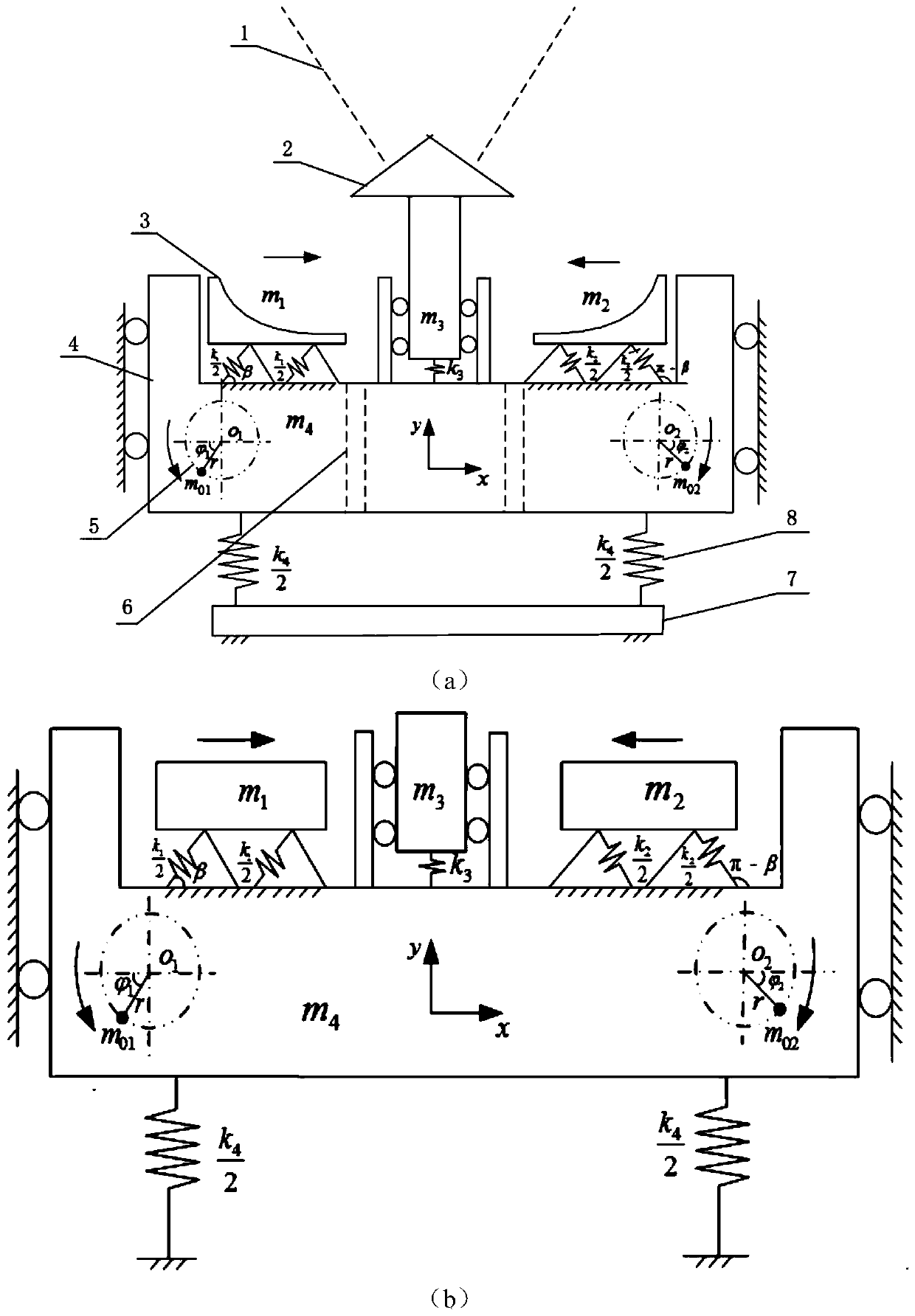
[0177] A self-synchronized drive anti-clogging vibrating feeder. Its dynamic model see figure 1 , including: exciter m 0i (i=1~2), plastid m i (i=1~4), spring k i (i=1~4). The model consists of two shakers and four masses. Plastids 1 and 2 move oppositely in the horizontal direction, and plastids 3 and 4 have no displacement in the x direction. And each vibrator rotates around its own axis of rotation to express.
[0178] The following are example data parameters for one of the vibratory feeders designed using this invention. The invention is not limited to this design parameter.
[0179] Spring rate: k 1y =k 2y =8000kN / m,k 3y =10000kN / m,k 4y =10kN / m;:
[0180] Damping factor: f 1y = f 2y =0.05
[0181] Plastid mass: m 1 =m 2 =1400kg, m 3 =1600kg;
[0182] r = 0.15m; z 2 =0.75; synchronous speed: ω m0 =833r / min—852r / min;
[0183] Shaker eccentric rotor mass: m 01 =m 02 =10kg, M 4 =m 4 +m 01 +m 02 =2020kg;
[0184] Motor parameters: rotor resistan...
PUM
 Abstract
Description
Claims
Application Information
 - R&D
- Intellectual Property
- Life Sciences
- Materials
- Tech Scout
- Unparalleled Data Quality
- Higher Quality Content
- 60% Fewer Hallucinations
Browse by: Latest US Patents, China's latest patents, Technical Efficacy Thesaurus, Application Domain, Technology Topic, Popular Technical Reports.
© 2025 PatSnap. All rights reserved.Legal|Privacy policy|Modern Slavery Act Transparency Statement|Sitemap|About US| Contact US: help@patsnap.com