
Underwater glider with memory-alloy driving attitude control

An underwater glider and memory alloy technology, which is applied to underwater ships, underwater operating equipment, motor vehicles, etc., can solve the problems that underwater glider does not have the ability to turn, the danger of electrical circuit short circuit, and takes up a lot of space. Good performance, saving space and load, and reducing response time

Active Publication Date: 2019-04-12
ZHEJIANG UNIV
View PDF6 Cites 3 Cited by
  • Summary
  • Abstract
  • Description
  • Claims
  • Application Information

AI Technical Summary

Problems solved by technology

[0003] However, the existing methods for changing the attitude angle of underwater gliders are as follows: one is to adjust the center of gravity of the underwater glider by using a sliding mass block, but the structure of the underwater glider is compact, and there is not enough space to realize this design; the other is to use The design of the fore and stern ballast tanks uses several water pumps to adjust the water volume in the fore and stern ballast tanks to adjust the center of gravity. In this design, the water pipes are arranged in the airtight underwater glider, and the absolute tightness of the water pipes and water pumps must be fully considered. , and detect the humidity, otherwise it will face the risk of short circuit in the electrical circuit; the third is to directly use the rotor, but the rotor consumes a lot of energy, so it is not suitable for carrying on the underwater glider carrying energy
[0004] To sum up, if the center of gravity adjustment module is used to change the attitude angle, another buoyancy adjustment module needs to be installed to realize snorkeling. This dual-module design takes up a lot of space and has a high load. Secondly, the existing propeller-free underwater gliders basically do not have steering ability

Method used


Image

  • Underwater glider with memory-alloy driving attitude control
  • Underwater glider with memory-alloy driving attitude control
  • Underwater glider with memory-alloy driving attitude control

Examples


Embodiment Construction

[0039] The specific embodiments of the present invention will be further described below in conjunction with the accompanying drawings.

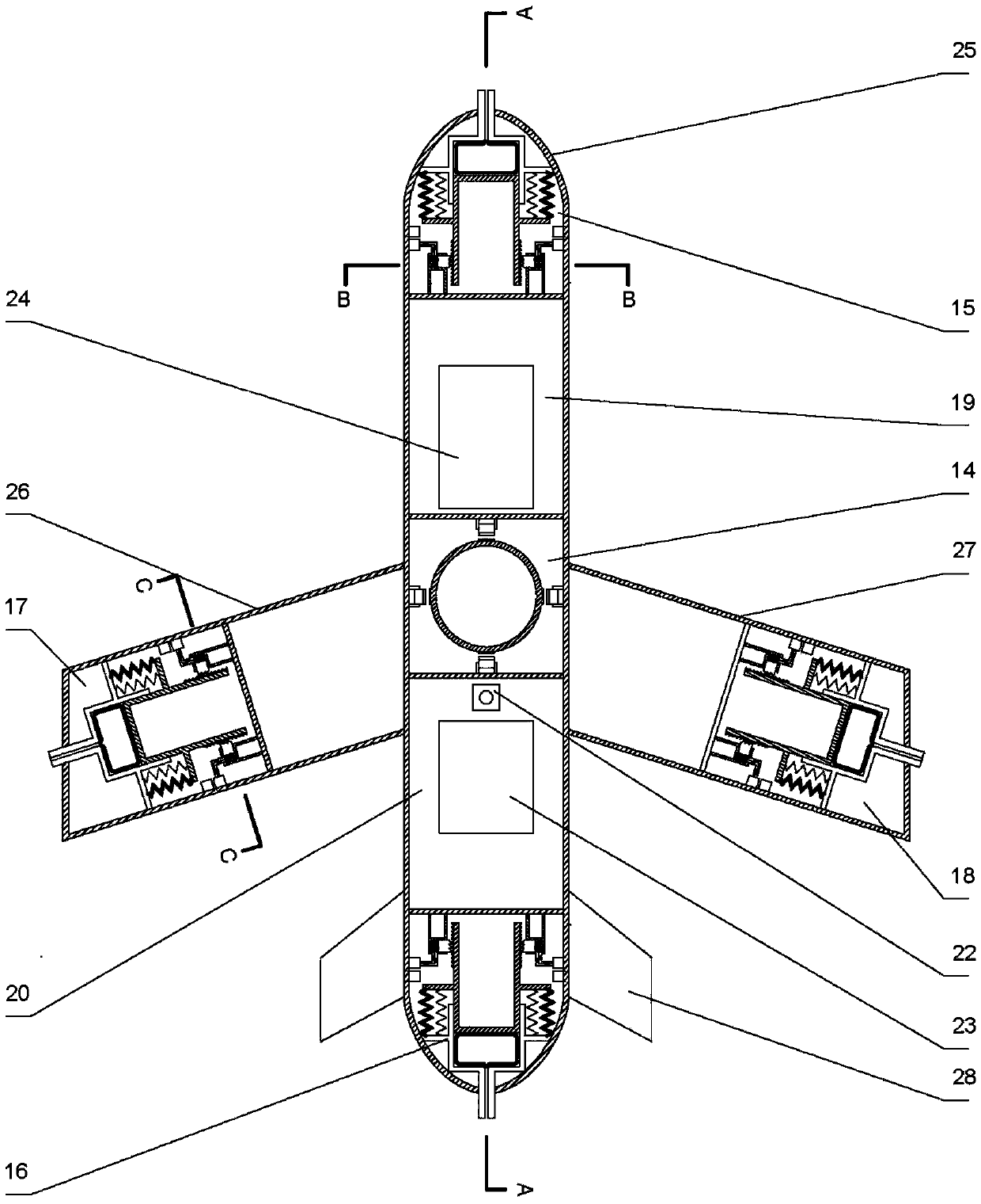
[0040] Such as image 3 and Figure 4As shown, the underwater glider comprises a fuselage 25, a left hang glider 26, a right hang glider 27 and an empennage 28; Empennage 28; Fuselage 25 bow interior is provided with bow buoyancy chamber 15, fuselage 25 middle interior is provided with central buoyancy chamber 14, fuselage 25 stern interior is provided with stern buoyancy chamber 16, and left hang glider 26 outer side interior A left wing buoyancy chamber 17 is provided, and a right wing buoyancy chamber 18 is arranged inside the outer part of the right hang glider 27; the inside of the fuselage 25 between the bow buoyancy chamber 15 and the central buoyancy chamber 14 forms a front control cabin 19, a central buoyancy chamber 14 and a stern buoyancy chamber. The inside of the fuselage 25 between the buoyancy chambers 16 forms the rear con...


PUM


Abstract

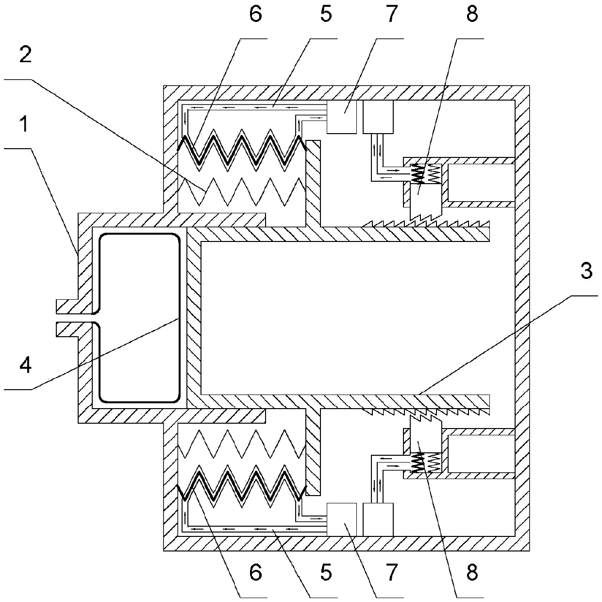
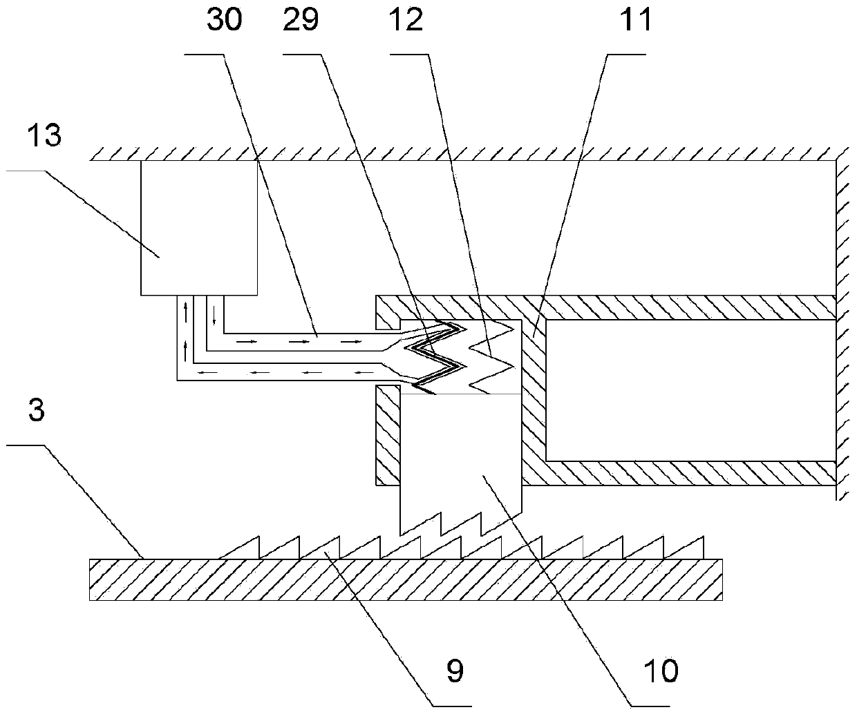
The invention discloses an underwater glider with memory-alloy driving attitude control. The underwater glider comprises a body, a left hang glider, a right hang glider and an empennage. A bow buoyancy chamber, a central buoyancy chamber, a stern buoyancy chamber, a left wing buoyancy chamber and the right wing buoyancy chamber are provided with underwater attitude control devices respectively. The underwater attitude control devices include variable buoyancy chambers and variable adjustment assemblies. A cavity is formed in a cylinder body in a hollow manner; a plunger is installed in a movable passage in the middle of the cylinder block and is in sealed connection with the movable passage; a water storage tank is installed in the movable passage of the cylinder body at the outer end surface of the plunger and is communicated with an external water environment through a through hole; and the plunger moves in the movable passage to drive the water storage tank to expand or contract. Atleast two variable adjusting assemblies are connected and installed between the plunger and the inner wall surrounding the cylinder body. According to the invention the variable buoyancy chamber is pulled to change the buoyancy by the phase change of the memory alloy wire; the deep water pressure can be carried; no moving sealing is involved; the response is fast and the energy consumption is low; and the underwater glider is suitable for the deep-water working environment.

Description

technical field [0001] The invention relates to an underwater glider, in particular to an underwater glider driven by a memory alloy and controlled by attitude. Background technique [0002] Underwater operations are very dangerous, so it is the most common measure to replace humans with underwater robots for long periods of time. In the field of marine resource exploration, underwater gliders have a series of technical advantages: superior space and time measurement density, long working hours and greater operational flexibility. [0003] However, the existing methods for changing the attitude angle of underwater gliders are as follows: one is to adjust the center of gravity of the underwater glider by using a sliding mass block, but the structure of the underwater glider is compact, and there is not enough space to realize this design; the other is to use The design of the fore and stern ballast tanks uses several water pumps to adjust the water volume in the fore and ste...

Claims


Application Information

Patent Timeline
Patent Type & Authority Applications(China)
IPC IPC(8): B63G8/22
CPCB63G8/22
Inventor 王林翔应子翔胡宇天
Owner ZHEJIANG UNIV
Learn More