Waste plastic regenerating system with iron removal function

A technology of waste plastics and regeneration system, applied in the direction of plastic recycling, mechanical material recycling, recycling technology, etc., can solve problems affecting production safety, endangering people's health, damaging the environment, etc., and achieve the effect of normal feeding and avoiding floating

Inactive Publication Date: 2019-04-12
界首市荣发再生资源有限公司
View PDF5 Cites 0 Cited by
  • Summary
  • Abstract
  • Description
  • Claims
  • Application Information

AI Technical Summary

Problems solved by technology

[0002] As the consumption of plastic products continues to increase, waste plastics are also increasing. At present, my country's waste plastics are mainly plastic films, plastic yarns and woven products, foam plastics, plastic packaging boxes and containers, daily-use plastic products, plastic bags and agricultural mulch. etc. It is understood that in 2004, domestic waste plastics reached about 11 million tons. If the storage, transportation, processing and application and post-treatment of these waste plastics are not appropriate, it will definitely damage the environment and endanger the health of the people. Crushing, cleaning, and granulation of plastics. During the crushing process of existing waste plastics, there will be a small amount of iron filings in the waste plastics, which will affect the subsequent granulation process. In addition, during the crushing process of waste plastics, there will be A large amount of powder is produced, affecting normal production safety

Method used


Image

  • Waste plastic regenerating system with iron removal function
  • Waste plastic regenerating system with iron removal function
  • Waste plastic regenerating system with iron removal function

Examples


Embodiment

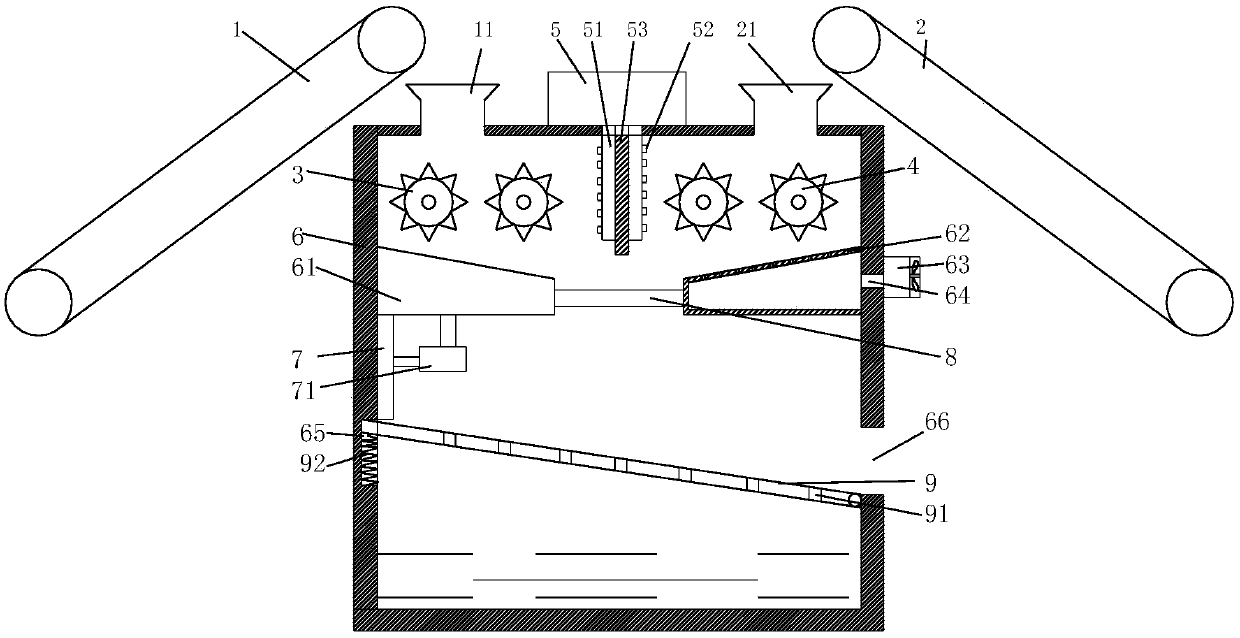
[0018] Such as Figure 1 to Figure 5 As shown, the present invention provides a waste plastic regeneration system with iron removal function, comprising a box body 6, a first feed port 11 and a second feed port 21 respectively arranged at both ends of the top of the box body 6, the first feed port A first conveyor belt 1 and a second conveyor belt 2 are provided above the port 11 and the first feed port 21, respectively, and a second conveyor belt 1 and a second conveyor belt 2 are respectively provided below the first feed port 11 and the second feed port 21 in the box body 6. One pulverizing roller 3, the second pulverizing roller 4;

[0019] Partition plate 53 is provided between the first crushing roller 3 and the first crushing roller 4, and the bottom of the first crushing roller 3 and the first crushing roller 4 is provided with a material guide box 61, and the inner wall between the material guide box 61 is fixed. There is a circular ferromagnet 8, the middle part of ...


PUM


Abstract

The invention discloses a waste plastic regenerating system with an iron removal function. The waste plastic regenerating system comprises a box body and further comprises a first feeding inlet and asecond feeding inlet which are formed in the two ends of the top of the box body correspondingly; a first conveyor belt and a second conveyor belt are arranged above the first feeding inlet and the second feeding inlet correspondingly; first smashing rollers and second smashing rollers are arranged on the positions, corresponding to the lower parts of the first feeding inlet and the second feedinginlet, in the box body correspondingly; a partition plate is arranged between the first smashing rollers and the second smashing rollers, and guiding boxes are arranged below the first smashing rollers and the second smashing rollers correspondingly; and a circular magnet is fixedly arranged on the positions, between the guiding boxes, on the inner walls. By arranging a water tank and an atomization spray head, powder in the box body can be pretreated, and thus the powder is prevented from floating in air; and by arranging an air blower, the bevel face of a discharging box can be blown up, and thus the situation that broken waste plastic is difficult to discharge normally due to dampness is avoided.

Description

Technical field: [0001] The invention relates to the field of plastic recycling equipment, in particular to a waste plastic recycling system with the function of removing iron. Background technique: [0002] As the consumption of plastic products continues to increase, waste plastics are also increasing. At present, my country's waste plastics are mainly plastic films, plastic yarns and woven products, foam plastics, plastic packaging boxes and containers, daily-use plastic products, plastic bags and agricultural mulch. etc. It is understood that in 2004, domestic waste plastics reached about 11 million tons. If the storage, transportation, processing and application and post-treatment of these waste plastics are not appropriate, it will definitely damage the environment and endanger the health of the people. Crushing, cleaning, and granulation of plastics. During the crushing process of existing waste plastics, there will be a small amount of iron filings in the waste plastic...

Claims


Application Information

Patent Timeline
IPC IPC(8): B29B17/02B29B17/04B02C4/08B02C4/28B02C23/18
CPCB02C4/08B02C4/28B02C23/18B29B17/02B29B17/04B29B2017/0272B29B2017/0484Y02W30/52Y02W30/62
Inventor 刘新安姜永俊
Owner 界首市荣发再生资源有限公司
Why Eureka
Try Eureka