
Membrane continuous preparation device and method for compound membrane with separating layer being PDMS

A membrane device and composite membrane technology, applied in semi-permeable membrane separation, chemical instruments and methods, membrane technology, etc., can solve the problems of long curing and drying time of coatings, inability to use continuous production, large water content, etc., and achieve improved curing. Effect of drying rate, shortening curing drying time, reducing crosslinking rate

Active Publication Date: 2019-04-12
BEIJING UNIV OF CHEM TECH
View PDF9 Cites 3 Cited by
  • Summary
  • Abstract
  • Description
  • Claims
  • Application Information

AI Technical Summary

Problems solved by technology

One is that a large amount of n-hexane (≥64.6%) is used to dissolve PDMS, resulting in a large amount of organic waste gas during the film making process, which damages the health of operators; at the same time, the post-treatment of organic waste gas further increases the production cost
Second, due to the flammable and explosive properties of n-hexane, this method needs to be dried naturally to volatilize n-hexane after coating the casting solution, and then dried under vacuum for 1-10 hours to obtain the PDMS / PVDF membrane; The curing and drying time of the composite film is much longer than the time allowed by the continuous production equipment, so this technical solution cannot be used in continuous production
But the problem that this method exists is that the water content is big in the film casting solution system (not given range in the claim, is 88wt% in the embodiment 2), polymer content is low (the not given range in the claim, in the embodiment 2 is 8.64wt%), resulting in a long coating curing and drying time (curing and drying at room temperature for 1 day)
Thereby, this technical scheme also can't be used for continuous production

Method used


Image

  • Membrane continuous preparation device and method for compound membrane with separating layer being PDMS
  • Membrane continuous preparation device and method for compound membrane with separating layer being PDMS
  • Membrane continuous preparation device and method for compound membrane with separating layer being PDMS

Examples


Embodiment approach

[0061] As mentioned earlier, the existing membrane-making process has three disadvantages. One is to use a large amount of n-hexane (≥64.6%) to dissolve PDMS, resulting in a large amount of organic waste gas in the membrane-making process. At the same time, the post-treatment of organic waste gas is further Increased production costs. The second is that due to the flammable and explosive properties of n-hexane, it needs to be dried naturally to volatilize n-hexane, resulting in the curing and drying time of the composite film being much longer than the allowed time of continuous production equipment. The third is that the water content in the casting liquid system is large and the polymer content is low, resulting in a long curing and drying time of the coating. For a long time, the above problems have become difficult technical problems in the art.

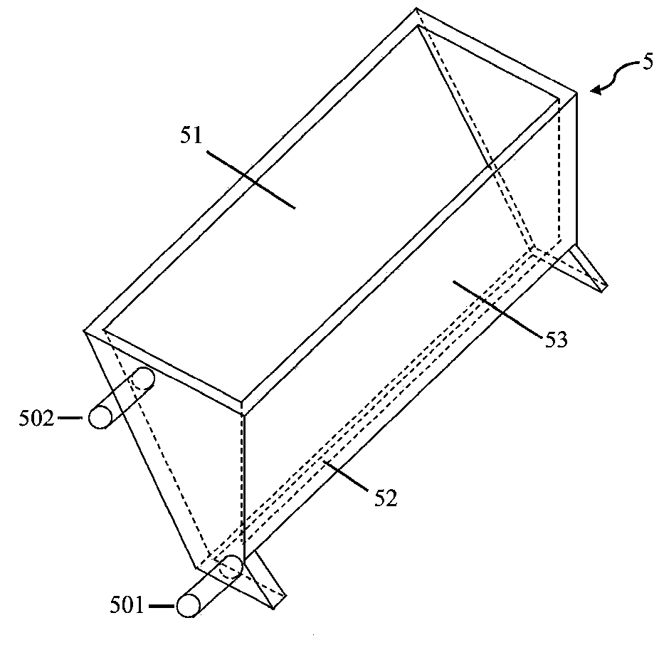
[0062] figure 1 It is a schematic diagram of a typical flat film continuous production device. Under the traction of the mot...

Embodiment 1

[0106] (1) the polytetrafluoroethylene ultrafiltration membrane is installed on the base film roll 1 as the base film 21, and one end of the base film 21 is pulled out to be wound around the scraping film roll 2 and the first winding roll 3 successively, and finally fixed On the II winding roller 4.

[0107] (2) Adjust the distance between the scraper 6 and the base film 21 to 40 μm, and the width of the base film 21 is 60 cm; start the thermostatic device 8 to keep the temperature of the casting solution tank 5 and the scraper 6 constant at 1° C.; 7. The internal temperature is controlled at 90°C.

[0108] (3) Mix 600g of hydroxyl-terminated polydimethylsiloxane with a viscosity of 10Pa·s, 120g of ethyl orthosilicate and 80g of water at 1°C, and stir mechanically at 800rpm for 1h; add 20g of dibutyltin dilaurate , stirring at room temperature for 5 minutes; vacuum degassing for 5 minutes to obtain casting solution 22.

[0109] (4) pour the casting solution 22 into the casti...

Embodiment 2

[0113] (1) the polytetrafluoroethylene ultrafiltration membrane is installed on the base film roll 1 as the base film 21, and one end of the base film 21 is pulled out to be wound around the scraping film roll 2 and the first winding roll 3 successively, and finally fixed On the II winding roller 4.

[0114] (2) Adjust the distance between the scraper 6 and the base film 21 to 40 μm, and the width of the base film 21 is 60 cm; start the thermostatic device 8 to keep the temperature of the casting solution tank 5 and the scraper 6 constant at 1° C.; 7. The internal temperature is controlled at 80°C.

[0115] (3) 600g of hydroxyl-terminated polydimethylsiloxane with a viscosity of 10Pa·s, 120g of tetraethyl orthosilicate and 80g of 3wt% dodecylbenzenesulfonic acid aqueous solution were mixed at 1°C, and the mixture was mixed at 800rpm Stir mechanically for 1 hour; add 20 g of dibutyltin dilaurate, stir at room temperature for 5 minutes; vacuum defoam for 5 minutes to obtain cas...


PUM

PropertyMeasurementUnit
viscosityaaaaaaaaaa
separation factoraaaaaaaaaa

Abstract

The invention relates to a membrane continuous preparation device and method for a compound membrane with a separating layer being PDMS. The method includes the steps that by decreasing reaction temperature and adding a reaction inhibitor, the rate of crosslinking of membrane casting liquor before coating is decreased greatly, and accordingly sufficient time is provided for coating of the membranecasting liquor. Meanwhile, after coating, a coating instantly enters a high-temperature environment, the reaction inhibitor is rapidly volatized within short time, and therefore the rate of solidifying and drying of the membrane casting liquor is increased greatly. In addition, organic solvent is not needed, accordingly, environmental pollution caused by usage of the organic solvent, harm to operators and other adverse factors are reduced, meanwhile, production costs are saved greatly, and economic benefits are increased.

Description

technical field [0001] The invention belongs to the technical field of membrane preparation, and in particular relates to a device and method for continuously preparing a composite membrane whose separation layer is PDMS. Background technique [0002] Composite membranes with polydimethylsiloxane (PDMS) as the separation layer are widely used in the fields of pervaporation and gas separation, especially in the production of bio-based chemicals and wastewater treatment, showing excellent separation performance. With the increasing emphasis on sustainable development of energy and environment, the demand for composite membranes with PDMS as the separation layer has also increased significantly. However, the current production process of PDMS composite membranes is cumbersome and inefficient, and cannot be produced in a continuous manner. [0003] Chinese patent CN 200910097955.2A discloses a method for preparing a PDMS / PVDF composite membrane. The composite membrane prepared ...

Claims


Application Information

Patent Timeline
Patent Type & Authority Applications(China)
IPC IPC(8): B01D67/00B01D69/12B01D71/70
CPCB01D67/0013B01D69/12B01D71/70
Inventor 秦培勇李树峰谭天伟司志豪李国桢
Owner BEIJING UNIV OF CHEM TECH
Learn More