Device and method for treating silt in fish pond
A treatment device, a technology for fish pond sludge, applied in the fields of sludge treatment, water/sludge/sewage treatment, dehydration/drying/concentrated sludge treatment, etc. Effect
- Summary
- Abstract
- Description
- Claims
- Application Information
AI Technical Summary
Problems solved by technology
Method used
Image

Examples
Embodiment 1
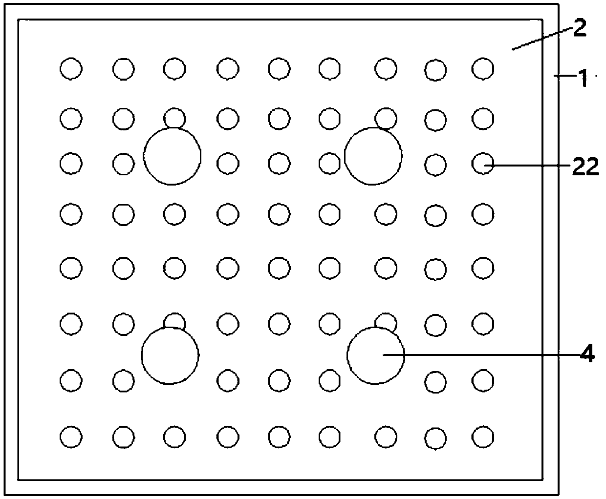
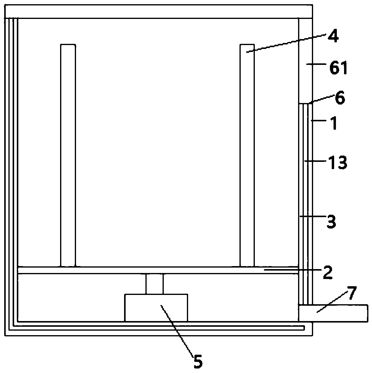
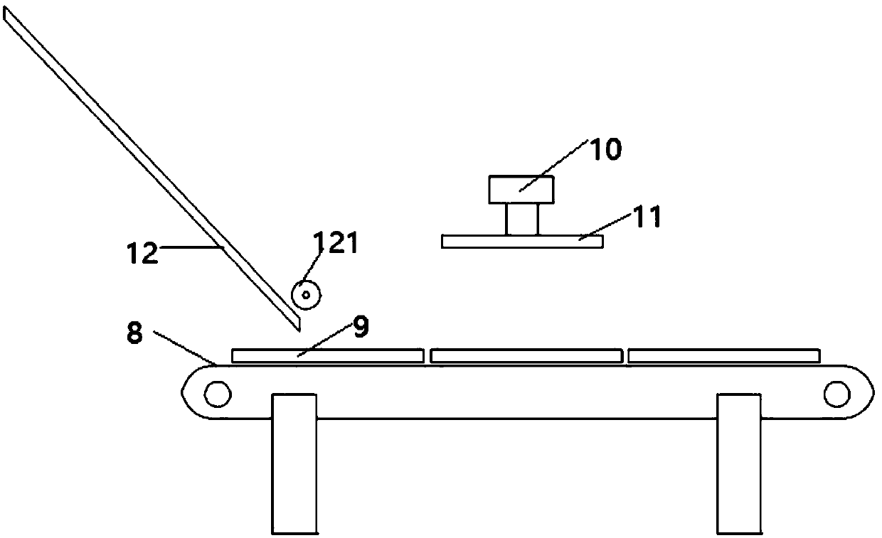
[0034] Such as figure 1 , figure 2 The illustrated embodiment is a fish pond sludge treatment device, comprising a sedimentation tank 1 with a rectangular cross section, a horizontal support plate 2 arranged in the lower part of the sedimentation tank, and 4 vertical support plates arranged on the inner side wall of the sedimentation tank 3. Four telescopic columns 4 on the horizontal support plate, a hydraulic cylinder 5 connected to the horizontal support plate at the bottom of the sedimentation tank, an opening 6 on the upper side wall of the sedimentation tank, and a cover plate of the sedimentation tank Rectangular grating panels on the lower surface, set as image 3 3 pallets 9 on the conveyer belt 8 shown, be located at the elevating device 10 above the conveying belt, the pressing plate 11 that is connected with elevating device, as Figure 4 Shown mud block drying rack 14; figure 1 As shown, the lower part of the settling tank is provided with a drainage pipe 7, a...
Embodiment 2
[0042] Embodiment 2 includes all structure and method parts of embodiment 1, such as Figure 5 As shown, the lower part of the outer peripheral surface of each telescopic column in embodiment 2 is provided with an annular groove 41 and 4 vertical chute 42 connected with the annular chute), and the inner edge of each fixing hole is provided with 4 Each positioning pin 211, the upper end of each telescopic column includes a circular plate 43, and the outer edge of each circular plate is located outside the outer peripheral surface of the corresponding telescopic column.
[0043] Lowering the height of each telescoping column is replaced by the following steps:
[0044] Rotate each telescopic column so that each positioning pin falls into the vertical chute of the corresponding telescopic column, and each telescopic column automatically moves downward under the action of gravity and silt pressure.
Embodiment 3
[0046] Embodiment 3 includes all structures and method parts of Embodiment 1. The lifting device of Embodiment 3 is a cylinder. Both the transmitter and the infrared receiver are electrically connected with the controller.
[0047] Step (6-4) of embodiment 1 is replaced by following steps:
[0048] The infrared transmitter emits infrared rays, and the infrared receiver receives infrared rays. The controller judges whether the tray is in place according to the signal contacted by the infrared receiver. When the tray passes by, the infrared rays will be blocked;
[0049] When the controller judges that there is a pallet under the pressing plate, the controller controls the telescopic rod of the cylinder to move downwards, and presses the rectangular blocks in the pallet into the independent space of the pallet respectively to obtain divided mud blocks, and puts the rectangular blocks on the pallet The mud block is poured on the mud block drying rack, and the dried mud block is ...
PUM
 Abstract
Description
Claims
Application Information
 - R&D
- Intellectual Property
- Life Sciences
- Materials
- Tech Scout
- Unparalleled Data Quality
- Higher Quality Content
- 60% Fewer Hallucinations
Browse by: Latest US Patents, China's latest patents, Technical Efficacy Thesaurus, Application Domain, Technology Topic, Popular Technical Reports.
© 2025 PatSnap. All rights reserved.Legal|Privacy policy|Modern Slavery Act Transparency Statement|Sitemap|About US| Contact US: help@patsnap.com