
Biliary drainage tube fixing device for post-orthotopic liver transplantation

A technology of fixing devices and drainage tubes, which is applied in the direction of catheters, other medical devices, and medical devices, can solve problems such as the inability to adjust the direction of fluid diversion, physical discomfort of patients, and pain of patients, and achieve good fixing effects, convenient operation, and ease of use. painful effect

Inactive Publication Date: 2019-04-09
王新
View PDF11 Cites 4 Cited by
  • Summary
  • Abstract
  • Description
  • Claims
  • Application Information

AI Technical Summary

Problems solved by technology

The device has a simple structure and a good fixing effect, but the binding force is relatively large, which may easily cause the patient's physical discomfort, and the direction of the fluid distribution cannot be adjusted, which will bring pain to the patient

Method used


Image

  • Biliary drainage tube fixing device for post-orthotopic liver transplantation
  • Biliary drainage tube fixing device for post-orthotopic liver transplantation
  • Biliary drainage tube fixing device for post-orthotopic liver transplantation

Examples


Embodiment 1

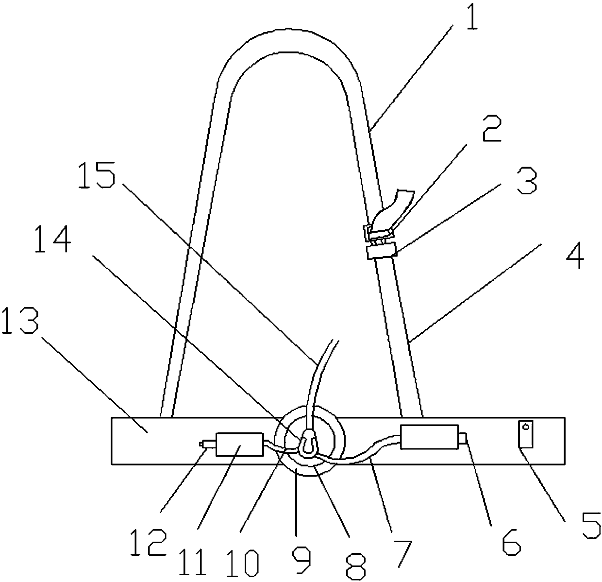
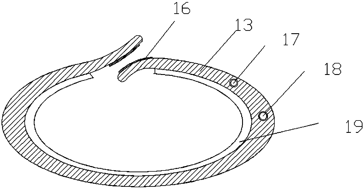
[0025] see Figure 1-2 , a biliary drainage tube fixation device after liver transplantation, comprising a horizontal band 13, a fixing seat 9 and a dividing tube 15. The divider pipe 15 is connected with the second shunt pipe 10 and the first shunt pipe 7 through the shunt fluid 14, the end of the second shunt pipe 10 is connected with the filter 12, and the end of the first shunt pipe 7 is connected with the one-way valve 6 , the second shunt tube 10 and the first shunt tube 7 communicate with the nutrient perfusion cavity and the bile drainage cavity respectively. The upper surface of the left end of the horizontal belt 13 is fixedly connected to one end of the left pull belt 1, the other end of the left pull belt 1 is connected with a male buckle 2, the male buckle 2 can control the length of the left pull belt 1, and the upper surface of the right end of the horizontal belt 13 is connected to At one end of the right drawstring 4, the other end of the right drawstring 4 i...

Embodiment 2

[0031] see Figure 4 , on the basis of Embodiment 1, the top of the groove 22 is fixedly provided with a magnet 29, and the bottom of the rotating groove 23 is fixedly provided with a magnet 29. When the rotating seat 8 is placed in the rotating groove 23, the magnets 29 attract each other. , so that the rotating seat 8 is fixed inside the fixed seat 9, and the setting of the magnet 29 makes the placement and removal of the rotating seat 8 more convenient and quick.


PUM


Abstract

The invention relates to the technical field of medical apparatus and instruments, and particularly discloses a biliary drainage tube fixing device for post-orthotopic liver transplantation. The biliary drainage tube fixing device for post-orthotopic liver transplantation comprises a cross belt, wherein the cross belt is fixedly connected with a left pull belt and a right pull belt; two fixing buckles, a fixing seat and a buckling portion are fixedly arranged on the outer surface of the cross belt; the cross belt has an inflatable air bag structure; an air inlet is formed in the upper surfaceof the cross belt; a rotating groove is formed in the fixing seat; a rotating seat is placed in the rotating groove; the fixing seat and the rotating seat are connected through a clamping device; a groove is formed in the bottom of the rotating seat; tooth grains are arranged on the inner side wall of the groove; a buckle is fixedly arranged on the upper surface of the rotating seat; a sliding groove is formed in the bottom of the fixing seat; a sliding block is placed in the sliding groove; the right end of the sliding groove is elastically connected with the right side surface of the slidinggroove through a spring; and a vertical clamping block is fixed on the upper surface of the sliding block. The biliary drainage tube fixing device for post-orthotopic liver transplantation has the advantages of convenience in mounting, simplicity in structure, convenience in operation, safety and reliability, adjustable angle of a flow distributing body, and capability of greatly relieving pain of a patient.

Description

technical field [0001] The invention relates to the technical field of medical equipment, in particular to a biliary drainage tube fixing device after liver transplantation. Background technique [0002] Percutaneous transhepatic biliary drainage is a percutaneous puncture of the biliary tract through the liver under the guidance of medical imaging equipment, and a catheter is placed for drainage. This operation can treat cholestasis, obstructive jaundice, secondary infection and other conditions caused by biliary obstruction, so as to achieve the therapeutic purpose of restoring liver and gallbladder function. Percutaneous transhepatic biliary drainage includes external drainage, internal drainage, and combined internal and external drainage. During the operation, a trocar is used to puncture the bile duct percutaneously through the liver; the needle core of the trocar is pulled out, the cannula is left in the body, and fine-tuned; Observe that it goes down through the ob...

Claims


Application Information

Patent Timeline
Patent Type & Authority Applications(China)
IPC IPC(8): A61M25/02
CPCA61M25/02A61M2025/0206A61M2210/1075A61M2210/005
Inventor 王新朱文燕许传屾
Owner 王新
Learn More